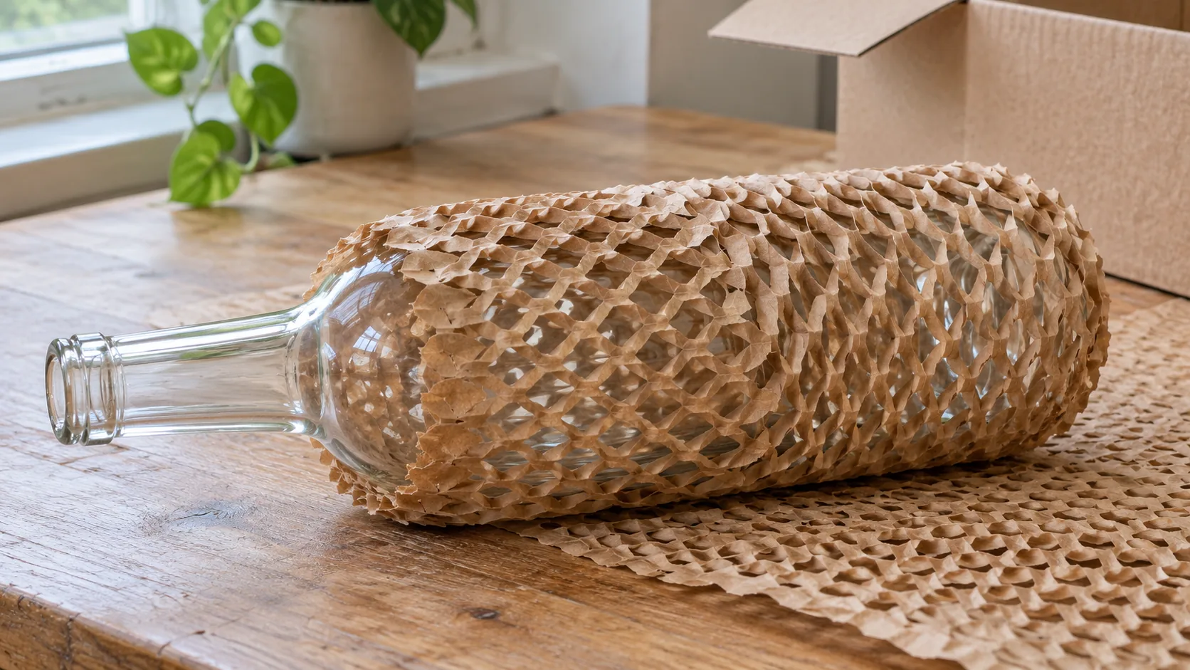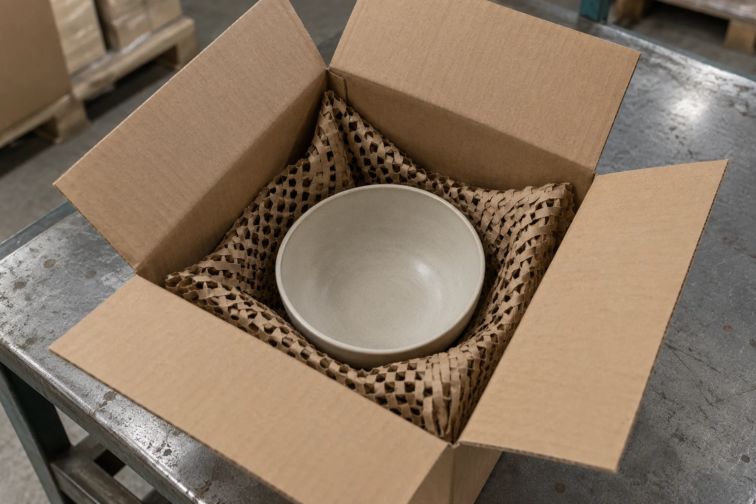
Integrating a paper void fill machine into a high-velocity fulfillment bench or spare-parts packing line requires matching the converter’s linear dispensing velocity (0.8–1.85 m/s), star-crimped bulk density (6.33–6.40 kg/m³), overhead chute geometry (1,150–1,450 mm above finished floor), and automatic guillotine cut mode to your carton void volume and product bearing pressure. Mounting a manual-tear dispenser outside the operator’s 350–500 mm reach envelope or placing single-ply 50–70 g/m² kraft fill underneath heavy parts (> 5–8 kg) wastes 3.5–6.6 seconds of cycle time per carton, causes 30–60 N wrist ulnar-deviation tear strain and 45°–90° lumbar trunk twisting, and leads to bottoming-out failure and product damage during transport drop impacts.
Engineering Workstation Baseline: Separate high-speed top void locking from bottom structural load bearing before selecting void fill packaging equipment. For light-to-medium headspace filling (product mass <= 5–8 kg, static bearing pressure < 1.5–2.0 kPa), specify an overhead cantilever or telescoping kraft paper void fill dispenser (1.4 m/s [84 m/min] linear feed, 380–760 mm fanfold width, 18:1–30:1 volumetric expansion) equipped with an automatic void fill paper cutter (< 0.18 s motorized shear), Electronic Delivery System (EDS) programmable length presets (±15 mm encoder accuracy), and a photoelectric chute take-away sensor (0.0 s operator machine-wait time). Position the discharge nozzle at 1,150–1,450 mm (45–57 in.) AFF tilted downward at 25°–35° within a 350–500 mm (14–20 in.) frontal reach zone per CDC/NIOSH Publication 2007-131 and ISO 11228-3.
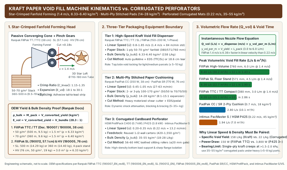
The matrix below defines the mechanical, volumetric, and ergonomic boundaries across the three primary equipment classes deployed at industrial packing stations: single-ply star-crimped fanfold kraft void-fill dispensers, multi-ply stitched paper cushioning converters, and corrugated cardboard perforators.
| Engineering Parameter | Tier 1: High-Speed Fanfold Kraft Void Fill Dispenser | Tier 2: Multi-Ply Crimped / Stitched Paper Cushion Converter | Tier 3: Industrial Corrugated Cardboard Perforator | Governing OEM Datasheet & Packout Boundary |
|---|---|---|---|---|
| Primary Packaging Task | High-speed top & lateral void filling (products <= 5–8 kg, static bearing pressure < 1.5–2.0 kPa) |
Dynamic shock cushioning, blocking & bracing, and coil fixating (products 5–35+ kg, drop G-force attenuation) |
High-density bottom load support, sharp flange isolation & heavy void bracing (repurposing incoming cartons) |
Separate void filling, restraint, and cushioning under our cardboard cushioning packout validation protocol. |
Linear Dispensing / Cutting Speed (v) |
0.8 to 1.85 m/s (1.4 m/s [84 m/min / 275.6 ft/min] standard on FillPak TT / TTC / SL; 0.8–1.2–1.4 m/s on FillPak) |
0.45 to 1.05 m/s (27–63 m/min / 90–205 ft/min; higher gear force to crimp & interlock 2–3 plies) |
0.20 to 0.35 m/s (12–21 m/min; e.g., 0.22 m/s [13.2 m/min] on intimus PacMaster S) |
Ranpak FillPak TTC (190007_EN_revB) at 1.4 m/s is 6.36× faster in linear velocity than 0.22 m/s (intimus PacMaster S). |
| Feedstock Format, Basis Weight & Width | 1-ply (or light 2-ply) fanfold stacks (adhesive splicing strip): 50 or 70 g/m² ("30–45#"), width 380 mm, 571 mm, or 760 mm (360–500 m/pack, 9.5–19.0 kg) |
2-ply or 3-ply rolls or fanfold stacks: 50/50, 50/70, 70/70, 50/50/50, 50/70/50, or 70/75 g/m² (100–170 g/m² total), width 380 to 760 mm |
Used incoming corrugated cartons (single-wall B/C 420–680 g/m² or double-wall BC/EB/AC 780–1,550 g/m²), 415–425 mm width, 10–20 mm gate |
FillPak SL (190012_EN) (57.12 / 57.15 cm, 4-pack magazine); PadPak SR (190001_EN_revB) (76 cm, 2-/3-ply); HSM ProfiPack overview. |
| Forming Kinematics & 3D Output Profile | Passive converging funnel cone + embossed pinch gears folding flat web inward into a 3D star-shaped column (Ø 110–180 mm) |
Counter-rotating stitching/crimping gears + forming chute interlocking plies into a structural central-seam cushion pad | Hardened 56–60 HRC alloy steel toothed slitting/scoring rollers (5 × 100 mm grid) expanding board into a connected lattice mat |
Star-crimped columns maximize volumetric loft per gram of fiber; stitched multi-ply and perforated corrugated mats carry static compressive deadweight. |
Volumetric Expansion (E_vol) & Bulk Density (ρ_bulk) |
18:1 to 30:1 bundle-to-void expansion (1.5 m³ yield per 38 cm pack; 3.0 m³ per 76 cm pack); ρ_bulk = 6.33–6.40 kg/m³ (4.5–8.5 kg/m³ band) |
8:1 to 15:1 expansion; ρ_bulk = 14–28 kg/m³ (high dynamic drop energy absorption) |
2.5:1 to 4.5:1 caliper/stack expansion; ρ_bulk = 35–55 kg/m³ (high static bearing stiffness, zero creep under heavy metal parts) |
1 kg of 50 g/m² FillPak paper fills 158 L of carton void (1,500 L ÷ 9.5 kg), whereas 1 kg of perforated corrugated board fills 18–28 L. |
Instantaneous Volumetric Flow (Q_vol) |
4.20 L/s (15.1 m³/h) on 380 mm head; 6.30 L/s (22.7 m³/h) on 571 mm head; 8.40 L/s (30.2 m³/h) on 760 mm head at 1.4 m/s |
1.80 to 3.50 L/s (6.5–12.6 m³/h depending on 2-ply vs. 3-ply crimp take-up ratio) |
0.40 to 1.94 L/s (up to 50–120 kg/h on HSM C400/P425; up to 7–11 m³/h = 1.94–3.05 L/s on intimus PacMaster S/VS) |
Fills a 12 L carton void in 1.43 to 2.86 s on a 1.4 m/s FillPak head vs. 6.2 to 18.0 s of equivalent corrugated perforator machine run time. |
| Electrical Power, Cut Method & Ergonomics | 150 to 200 W (100–230 V 1~); Automatic guillotine cut (< 0.18 s, 0 N tear) + EDS (TTC / SL / HV) or Manual tear (18.6 cm perf on TT / M) |
350 W (PadPak CC) to 770 W (PadPak SR) (100–240 V 1~); heavy-duty motorized shear blade + EDS/foot switch |
700 W (C400) to 2,000–4,000 W (P425 / PacMaster S) (230 V 1~ or 400 V 3~); pass-through feed with side-trim blade |
A 150 W FillPak TTC draws 3.9%–7.5% the electrical power of a 2.0–3.8 kW floor corrugated perforator and mounts directly over the carton. |
High-speed kraft paper void fill dispenser kinematics vs corrugated perforators
Converging funnel star-crimping mechanics vs toothed roller slitting
A fanfold kraft paper dispenser (such as the Ranpak FillPak TTC, FillPak TT, FillPak SL, or FillPak high-volume converter) and an industrial corrugated cardboard perforator (HSM ProfiPack C400 / P425 or intimus PacMaster S / VS) operate on fundamentally different mechanical principles and serve distinct load paths inside a shipping container:
- Star-Crimped Fanfold Kraft Paper Void Fill Kinematics (
0.8–1.85 m/s): A kraft paper void fill dispenser draws flat single-ply (50 or 70 g/m²,"30–45#") or light two-ply fanfold kraft paper vertically from a floor or under-bench stack through a passive converging conical forming funnel. As the flat sheet (380 mm,571 mm, or760 mmwide) converges into the narrow throat of the cone, the outer paper edges roll inward toward the center while a pair of counter-rotating embossed gear-tooth pinch wheels pull the gathered web at0.8 to 1.85 m/s(1.4 m/s[84 m/min/275.6 ft/min] standard across the RanpakFillPakseries). The intermeshing gear teeth mechanically crimp and lock the longitudinal center fold, transforming the flat sheet into a resilient, three-dimensional star-shaped column (Ø 110–180 mmeffective cross-section) filled with trapped air pockets. - Multi-Ply Stitched / Crimped Paper Cushioning Kinematics (
0.45–1.05 m/s): By contrast, heavy-duty paper cushioning machines—documented in the Ranpak PadPak SR (190001_EN_revB) (770 W,175 kg,760 mmwidth) andPadPak CC(190004_EN_revB,350 W,50 kg,380 mmwidth) technical folders—pull 2-layer or 3-layer kraft webs (50/50,50/70,70/70,50/50/50,50/70/50, or70/75 g/m², totaling100 to 170 g/m²) through high-pressure forming and stitching gears. That multi-ply folding and longitudinal seam interlocking consumes1.35 to 1.65 mof flat paper per meter of finished pad (linear crimp take-up ratio C_linear = 1.35–1.65), producing a structural shock-absorbing pad at14 to 28 kg/m³bulk density. - Corrugated Cardboard Perforator Kinematics (
0.20–0.35 m/s): As detailed in our heavy duty cardboard shredder selection guide for double-wall boxes and blade types and throughput model, a corrugated perforator uses twin hardened steel rollers (56–60 HRC) to pierce, slit, and score3 to 15 mmincoming corrugated board at0.20 to 0.35 m/s(0.22 m/s[13.2 m/min] on the400 V / 4.0 kWintimus PacMaster S / VS), expanding the rigid board into a dense structural lattice mat (35 to 55 kg/m³). Similarly, surface-protection converters such as theRanpak Geami WrapPak HV(0–0.75 m/s, expanding80 g/m²die-cut kraft1.68×with a22 g/m²tissue interleaf, analyzed in honeycomb paper wrap versus shredded cardboard) wrap fragile glazed surfaces rather than dosing high-speed volumetric void fill.
Volumetric expansion ratio (E_vol), converted bulk density (ρ_bulk), and nozzle flow (Q_vol) equations
To compare a paper void fill machine rated in linear meters per second (m/s) against a carton void measured in liters (L) or a corrugated perforator rated in kilograms per hour (kg/h), industrial engineers apply four governing material-balance equations:
- Linear Crimp Take-Up Ratio (
C_linear):C_linear = L_unexpanded ÷ L_dispensed_pad(Typically1.15 to 1.35for single-ply star-crimped void fill because longitudinal gear embossing gathers the web into 3D pleats, compared to1.35 to 1.65for multi-ply stitched cushioning pads.) - Bundle-to-Void Volumetric Expansion Ratio (
E_vol):E_vol = V_converted_yield ÷ V_fanfold_bundle - Operational Converted Bulk Density (
ρ_bulk, inkg/m³org/L):ρ_bulk = M_pack ÷ V_converted_yield - Instantaneous Volumetric Dispensing Rate (
Q_vol, inL/sandm³/h):Q_vol (L/s) = v_dispense × y_vol_per_m = (1,000 × w_paper × σ_paper × v_dispense) ÷ (ρ_bulk × C_linear)wherey_vol_per_m = (1,000 × V_converted_yield) ÷ L_packis the converted void volume yielded per linear meter of paper (L/m).
Worked OEM Proofs from Ranpak, HSM, and intimus Datasheets
-
Proof 1 — Compact
380 mm(38 cm) Fanfold Dispenser (Ranpak FillPak TTC / TT / M, Docs.190007_EN_revB&190006_EN_revB):- 50 g/m² Standard Fanfold Pack: Unexpanded sheet length
L_pack = 500 m, paper widthw_paper = 0.38 m(sheet area = 190 m²), published average pack weightM_pack = 9.5 kg(190 m² × 0.050 kg/m² = 9.50 kg). A palletized fanfold bundle (~380 × 270 × 520 mm) occupiesV_fanfold_bundle = 0.053 m³(53 L) of under-bench storage (solid cellulose fiber volume at ~750 kg/m³ sheet density is 0.0127 m³). Published average converted yield isV_converted_yield = 1.5 m³(1,500 L) per pack. - Volumetric Expansion Ratio (
E_vol):E_vol = 1.50 m³ ÷ 0.053 m³ = 28.3 : 1(sitting squarely inside the18:1 to 30:1operational expansion envelope depending on packer tuck compression). - Converted Bulk Density (
ρ_bulk):ρ_bulk (50 g/m²) = 9.5 kg ÷ 1.5 m³ = 6.33 kg/m³(6.33 g/L, or157.9 Lof expanded void fill per kilogram of paper). For the70 g/m²pack (L_pack = 360 m,M_pack = 9.6 kg,V_converted_yield = 1.5 m³[1,500 L]):ρ_bulk (70 g/m²) = 9.6 kg ÷ 1.5 m³ = 6.40 kg/m³(6.40 g/L, because the stiffer70 g/m²fiber holds a wider star cross-section, yielding4.17 L/mvs.3.00 L/mon50 g/m²). - Instantaneous Volumetric Flow (
Q_vol) atv_dispense = 1.4 m/s: Withy_vol_per_m = 1,500 L ÷ 500 m = 3.00 L/mon50 g/m²stock:Q_vol = 1.4 m/s × 3.00 L/m = 4.20 L/s(15.12 m³/hinstantaneous nozzle flow), filling a12.0 Lshipping carton void in2.86 seconds(or 2.06 secondsusing70 g/m²stock at4.17 L/m).
- 50 g/m² Standard Fanfold Pack: Unexpanded sheet length
-
Proof 2 — Floor-Standing
571 mm(FillPak SL, Doc.190012_EN) and760 mm(FillPakHigh-Volume, Doc.190005_EN_revB) Converters:FillPak SL(57.12 cm50 g/m²[500 m,14.29 kg] or57.15 cm70 g/m²Greenline [360 m,14.40 kg]): Scaling width by571.2 ÷ 380 = 1.503×increases linear volumetric yield toy_vol_per_m = 4.50 L/m(2.25 m³per pack,9.0 m³[9,000 L] across the 4-pack base magazine). At1.4 m/s, instantaneous nozzle flow reachesQ_vol = 1.4 m/s × 4.50 L/m = 6.30 L/s(22.68 m³/h), filling a12.0 Lvoid in1.90 seconds.FillPakHigh-Volume (76 cm[760 mm],50 g/m²,500 m,19.0 kgpack mass,3.0 m³[3,000 L] published yield):ρ_bulk = 19.0 kg ÷ 3.0 m³ = 6.33 kg/m³, andy_vol_per_m = 3,000 L ÷ 500 m = 6.00 L/m. At its top selectable speed of1.4 m/s(0.8 / 1.2 / 1.4 m/sthree-speed selector), instantaneous nozzle output reachesQ_vol = 1.4 m/s × 6.00 L/m = 8.40 L/s(30.24 m³/h), filling a12.0 Lvoid in1.43 seconds.
-
Proof 3 — Direct Contrast with Corrugated Cardboard Perforators (
HSM ProfiPack C400 / P425&intimus PacMaster S / VS):- An intimus PacMaster S (
400 V3-phase,4.0 kW,425 mmwidth,v_feed = 0.22 m/s[13.2 m/min], rated up to7.0 m³/h=1.94 L/svolumetric mat output) or HSM ProfiPack P425 (up to 80–120 kg/hatρ_bulk = 35–55 kg/m³, equivalent to0.50 to 0.95 L/sof expanded mat volume) operates at1/6ththe linear speed and1/2 to 1/9ththe instantaneous volumetric flow of a1.4 m/spaper void fill machine, while producing a mat that is5.5× to 8.7×denser.
- An intimus PacMaster S (
| Ranpak / OEM Model Reference | Document Number | Converter Dimensions & Mass | Electrical Rating | Linear Dispensing Speed (v) |
Cut & Control Method | Paper Width & Basis Weight (σ) |
Pack Length & Mass (M_pack) |
Converted Yield (V_yield) & Density (ρ_bulk) |
|---|---|---|---|---|---|---|---|---|
| Ranpak FillPak M (Manual Non-Electric) | 190008_EN_revB |
54 × 40 × 67–103 cm; 4 kg |
None (0 W, manual pull) |
Operator pull speed (~0.3–0.6 m/s) |
Manual tear (perforation every 18.6 cm) |
38 cm (380 mm); 50 or 70 g/m² |
500 m (9.5 kg) or 360 m (9.6 kg) |
1.5 m³ (1,500 L/pack); 6.33–6.40 kg/m³ |
| Ranpak FillPak TT (Table-Top / Stand Manual Tear) | 190006_EN_revB |
43 × 45 × 46 cm; 8 kg head |
100–230 V, 150 W |
1.4 m/s (84 m/min / 275.6 ft/min) |
Foot pedal; Manual tear (perforation every 18.6 cm) |
38 cm (380 mm); 50 or 70 g/m² |
500 m (9.5 kg) or 360 m (9.6 kg) |
1.5 m³ (1,500 L/pack); 6.33–6.40 kg/m³; 4.20 L/s |
| Ranpak FillPak TTC (Table-Top / Stand Auto-Cut) | 190007_EN_revB |
43 × 45 × 46 cm; 10 kg head |
100–230 V, 150 W |
1.4 m/s (84 m/min / 275.6 ft/min) |
Automatic guillotine cut (< 0.18 s) + EDS mode + foot pedal |
38 cm (380 mm); 50 or 70 g/m² |
500 m (9.5 kg) or 360 m (9.6 kg) |
1.5 m³ (1,500 L/pack); 6.33–6.40 kg/m³; 4.20 L/s |
| Ranpak FillPak SL (Telescoping 4-Pack Stand) | 190012_EN |
64 × 77.8 × 230–260 cm; 103 kg |
100–230 V (50/60 Hz), 150 W |
1.4 m/s (84 m/min / 275.6 ft/min) |
Automatic cut + Foot pedal & EDS modes + head tilt |
57.12 cm (50 g/m²) or 57.15 cm (70 g/m²) |
500 m (14.29 kg) or 360 m (14.40 kg); 4-pack stand |
~2.25 m³/pack (9.0 m³ on 4-pack stand); 6.30 L/s |
| Ranpak FillPak (High-Volume Over-Conveyor) | 190005_EN_revB |
90 × 97 × 235 cm; 176 kg |
100–230 V, 200 W |
3 speeds: 0.8 – 1.2 – 1.4 m/s |
Automatic cut + EDS mode + foot pedal |
76 cm (760 mm); 50 g/m² single-layer |
500 m (19.0 kg average pack weight) |
3.0 m³ (3,000 L/pack); 6.33 kg/m³; 8.40 L/s |
| Ranpak PadPak CC / PadPak SR (Multi-Ply Cushion) | 190004_EN_revB / 190001_EN_revB |
CC: 51×81×55 cm (50 kg); SR: 94×100×193–225 cm (175 kg) |
CC: 350 W; SR: 770 W (230 V) |
0.45–1.05 m/s |
Heavy automatic shear cut + EDS / foot pedal |
CC: 38 cm (1–2 ply); SR: 76 cm (2–3 ply 100–170 g/m²) |
Rolls or fanfold packs (50/50 to 70/70/50 g/m²) |
High-density shock pads (14–28 kg/m³); 1.8–3.5 L/s |
Overhead swivel boom geometry and automated EDS length control
Mounting frame configurations and the four geometric integration parameters
Unlike a 103–175 kg floor-standing corrugated shredder that occupies a conversion bay and feeds mobile gaylord carts, a paper void fill machine (8–10 kg converter head on the FillPak TT / TTC) is engineered to dispense directly into the open shipping carton on the packing bench or roller conveyor. As documented in the Ranpak FillPak SL specification folder (190012_EN) and FillPak TTC folder (190007_EN_revB), workstation layout is governed by four geometric design parameters:
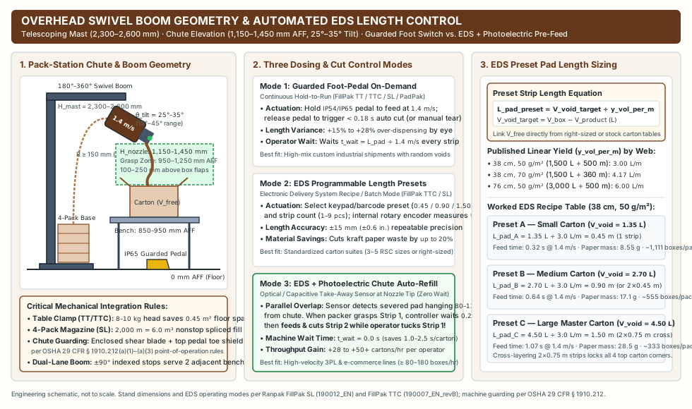
- Mounting Frame Architecture (Table C-Clamp vs. Telescoping Floor Stand vs. Over-Conveyor Swivel Jib Boom):
- Compact Table-Clamp / Tilt Mount (
FillPak TT / TTC,43 × 45 × 46 cm,8–10 kg): Clamps directly to the rear or side frame of a750–900 mmdeep packing bench, saving0.45 m²of floor footprint and drawing fanfold paper vertically from a single500 m(9.5 kg) under-bench pack. - Telescoping Floor Stand (
FillPak SL,64 × 77.8 × 230 [low]–260 [high] cm,103 kg): Straddles the rear of the packing table or conveyor via manual or semi-automatic height adjustment. On theFillPak SL, the integrated base paper stand holds 4 fanfold packs (4 × 500 m = 2,000 m, yielding6.0 to 9.0 m³of continuous void fill) joined by factory adhesive splicing strips, so the tail of Pack 1 automatically pulls the leading edge of Pack 2 into the feed rollers via the load button without operator re-threading. - Articulating Over-Conveyor Cantilever / Jib Boom (
180°–360°Horizontal Swivel,450–850 mmCantilever Reach): Suspends the converter head directly above multi-line roller conveyors, allowing a single dispenser head with±90°indexed stops to swing between two adjacent packing stations.
- Compact Table-Clamp / Tilt Mount (
- Chute Discharge Nozzle Elevation (
H_nozzle = 1,150 to 1,450 mm[45 to 57 in.] Above Finished FloorAFF): Standard ergonomic standing benches sit atH_bench = 850 to 950 mm(33.5–37.4 in.) AFF (or750–850 mmwhen fitted with a100–120 mmgravity roller deck), and typical corrugated cartons addH_carton = 150 to 400 mmof sidewall height (placing the open top flaps at1,000 to 1,300 mmAFF). Setting the converter discharge nozzle at1,150 to 1,450 mmAFF positions the paper exit100 to 250 mm(4–10 in.) directly above the open carton rim and squarely inside the standing operator’s elbow-to-shoulder vertical comfort window (950–1,250 mmAFF). - Converter Head Downward Tilt Angle (
θ_tilt = 15° to 45°below horizontal;25°–35°optimal): If a converter discharges horizontally (0°), the stiff1.4 m/sstar-crimped paper tube shoots across the top of the carton toward the packer’s chest. Utilizing the head-tilt mechanism (documented on the FillPak TTC and FillPak SL) at25° to 35°downward inclination aims the paper trajectory directly into the open carton center at a300–450 mmhorizontal stand-off distance, allowing gravity and chute geometry to pre-coil the strip into the void. - Low-Tension Fanfold Infeed Guide Path (
R >= 150 mm,±5°Centerline Alignment): Because50 g/m²recycled kraft paper has lower cross-web tear resistance than70 g/m²virgin kraft, the rear guide chute between the floor fanfold stack and the converter funnel intake must maintain a smooth entry bend radius (R >= 150 mm) aligned within±5°of the converter centerline. Misaligned floor stacks snag paper edges and cause premature perforation separation during1.4 m/sacceleration ramps.
Three operating and dosing control modes: Guarded foot switch, EDS presets, and photoelectric auto-refill
Modern void fill packaging equipment replaces manual pulling with microprocessor-controlled drive and guillotine actuation across three selectable operating modes, governed by OSHA 29 CFR § 1910.212 (General requirements for all machines) point-of-operation guarding rules:
| Dosing & Cut Control Mode | Sensor, Encoder & Blade Actuation Logic | Strip Length Accuracy & Material Variance | Operator Machine-Wait Time (t_wait per Strip) |
Optimal Pack-Station Deployment |
|---|---|---|---|---|
Mode 1: Guarded Foot-Pedal On-Demand (Continuous Hold-to-Run) |
Operator depresses an IP54 / IP65 guarded industrial footswitch equipped with a top steel toe shield (preventing accidental actuation per OSHA 29 CFR § 1910.212). Pinch gears feed paper at 1.4 m/s while held; releasing the pedal halts the motor and triggers the enclosed guillotine blade (< 0.18 s cut on FillPak TTC, or manual tear at 18.6 cm perf on FillPak TT). |
Visual operator estimation results in +15% to +28% over-dispensing variance across shift workers. |
t_wait = L_pad ÷ v_dispense during every pedal press (e.g., 0.43 s for 0.60 m, 0.64 s for 0.90 m, 1.07 s for 1.50 m). |
High-mix custom industrial shipments where every box contains irregular parts and variable void volumes. |
Mode 2: EDS (Electronic Delivery System) Programmable Length Presets (Batch Mode) |
Keypad or WMS barcode selects programmable strip lengths (e.g., Preset A = 0.45 m, Preset B = 0.90 m, Preset C = 1.50 m) and strip counts (1–9 strips/box). Internal rotary shaft encoder counts paper travel to ±15 mm (±0.6 in.) and actuates the automatic void fill paper cutter inside an interlocked discharge chute (preventing finger reach to the shear zone per 29 CFR § 1910.212(a)(3)). |
±15 mm repeatable precision; eliminates 15%–25% visual over-dispensing (achieving up to 20% kraft paper reduction). |
t_wait = L_pad ÷ v_dispense triggered by a single pedal tap or keypad press (hands remain free to position product). |
Standardized 3PL and e-commerce carton suites (3 to 5 standard RSC sizes or right-sized cartons with known residual void V_free). |
Mode 3: EDS + Photoelectric / Capacitive Chute Take-Away Sensor (Pre-Feed Refill) |
An optical retro-reflective or capacitive sensor at the discharge nozzle tip detects a severed paper strip hanging 80–120 mm out of the chute. The instant the operator grasps and pulls Strip 1 (clearing the optical beam), the controller waits 0.15–0.25 s clearing delay, then automatically feeds and pre-cuts Strip 2 while the operator tucks Strip 1 and tapes the carton. |
±15 mm precision plus zero operator rush or short-pulling. |
t_wait = 0.0 s (eliminates 1.0 to 2.5 s per carton of machine dispense & cut waiting) via parallel machine-operator overlap! |
High-velocity fulfillment pack stations (80 to 180+ cartons/hr per operator) where parallel pre-feeding directly boosts line capacity. |
Preset pad length calibration formula (L_pad_preset)
To program EDS batch presets from the internal carton free volume (V_free = V_box − V_product) established in our on-demand box sizing and cushioning guide, divide the target residual void volume V_void_target (L) by the converter’s linear volumetric yield y_vol_per_m (L/m):
L_pad_preset (m) = V_void_target (L) ÷ y_vol_per_m (L/m) = (V_void_target × ρ_bulk_installed × C_linear) ÷ (1,000 × w_paper × σ_paper)
Where published Ranpak linear volumetric yields (y_vol_per_m = V_converted_yield ÷ L_pack) are:
380 mm(38 cm),50 g/m²(FillPak TTC / TT,1,500 L ÷ 500 m):y_vol_per_m = 3.00 L/m(19.0 gof paper per linear meter).380 mm(38 cm),70 g/m²(FillPak TTC / TT,1,500 L ÷ 360 m):y_vol_per_m = 4.17 L/m(26.6 gof paper per linear meter).571 mm(57.1 cm),50 g/m²(FillPak SL,2,250 L ÷ 500 m):y_vol_per_m = 4.50 L/m(28.6 gof paper per linear meter).760 mm(76 cm),50 g/m²(FillPakHigh-Volume,3,000 L ÷ 500 m):y_vol_per_m = 6.00 L/m(38.0 gof paper per linear meter).
Worked EDS Recipe Calibration (380 mm, 50 g/m² FillPak TTC at y_vol_per_m = 3.00 L/m, v = 1.4 m/s):
- Preset A — Small Carton (
V_void_target = 1.35 L):L_pad_A = 1.35 L ÷ 3.00 L/m = 0.45 m(1 strip × 0.45 m, machine feed time0.45 ÷ 1.4 = 0.32 s, paper mass0.45 m × 19.0 g/m = 8.55 g, yielding1,111 cartons per 500 m pack). - Preset B — Medium Carton (
V_void_target = 2.70 L):L_pad_B = 2.70 L ÷ 3.00 L/m = 0.90 m(1 strip × 0.90 mor2 strips × 0.45 m, machine feed time0.64 s, paper mass17.10 g, yielding555 cartons per 500 m pack). - Preset C — Large Master Carton (
V_void_target = 4.50 L):L_pad_C = 4.50 L ÷ 3.00 L/m = 1.50 m(programmed as2 cross-layered strips × 0.75 mto lock all four upper carton corners, total feed time1.07 s, paper mass28.50 g, yielding333 cartons per 500 m pack).
Pack-station ergonomics: ISO 11228-3, NIOSH reach zones, and single-hand tucking
Anthropometric reach envelopes (CDC/NIOSH 2007-131 and ISO 11228-3 / OCRA)
In high-throughput e-commerce and spare-parts distribution centers, a single packing operator processes 400 to 900 cartons per 8-hour shift (50 to 112 cartons/hour, executing 800 to 2,700 repetitive upper-limb grasp, separation, and tuck actions per shift). Under ISO 11228-3 (Ergonomics — Manual handling — Part 3: Handling of low loads at high frequency)—which standardizes the OCRA (Occupational Repetitive Actions) risk index for upper-limb tasks exceeding 1 hour/shift—and CDC/NIOSH Publication No. 2007-131 (Ergonomic Guidelines for Manual Material Handling), workstation geometry must keep technical action frequency, pinch/tear force, wrist posture, and torso angles within neutral biomechanical thresholds.
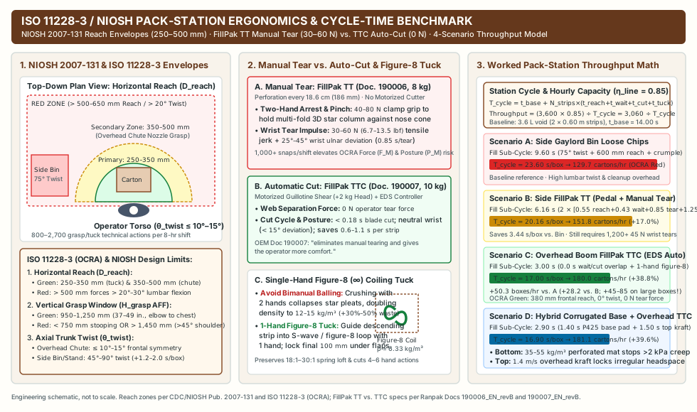
Biomechanical Parameter (ISO 11228-3 & NIOSH 2007-131) |
Optimal Ergonomic Green Zone (OCRA Green) |
High-Risk Workstation Violation (OCRA Red / Yellow) |
Biomechanical Consequence & Cycle-Time Penalty |
|---|---|---|---|
Horizontal Reach Distance (D_reach from Torso Centerline) |
Primary Zone: 250–350 mm (10–14 in.) for carton tucking; Secondary Chute Zone: 350–500 mm (14–20 in.) for overhead paper nozzle grasp. |
> 500–650 mm (> 20–26 in.) (reaching across a wide bench or into a floor gaylord bin of loose shredded cardboard). |
Reaching > 500 mm forces full elbow extension plus > 20°–30° anterior spinal flexion, multiplying L5/S1 lumbar disc moment (NIOSH 2007-131) and adding +0.8–1.5 s per reach. |
Vertical Grasp Height (H_grasp Above Finished Floor AFF) |
950 to 1,250 mm (37 to 49 in.) AFF (between standing elbow height ~950–1,050 mm and mid-chest height ~1,200–1,250 mm, fed by a nozzle at 1,150–1,350 mm AFF). |
< 750 mm (< 29.5 in., stooping into deep floor bins) OR > 1,450 mm (> 57 in., reaching above shoulder level). |
Grasping above shoulder height forces shoulder flexion/abduction > 45°–80°, flagged by ISO 11228-3 as a primary driver of supraspinatus tendonitis and subacromial impingement. |
Axial Trunk Rotation (θ_twist) & Lateral Bending |
<= 10°–15° symmetric frontal presentation (overhead boom suspends chute directly on or within ±15° of the carton packing centerline). |
> 15°–20° (typically 45°–90° when pulling paper or scooping mats from a stand/bin behind or beside the operator). |
Eliminating 60°–90° torso twists (800–1,500 times/shift) removes asymmetrical paraspinal shear loading and saves 1.2–2.0 seconds of whole-body turn time per carton. |
Web Separation Force (F_tear) & Wrist Posture (P_M) |
0 N operator tear force with neutral wrist (< 15° deviation) via an automatic void fill paper cutter (FillPak TTC / SL / FillPak, < 0.18 s cut). |
30 to 60 N (6.7–13.5 lbf) peak manual jerk-tear force + 25°–45° wrist ulnar deviation and rapid pronation across 18.6 cm perforations (FillPak TT / M). |
Executing 1,000+ manual 30–60 N wrist-snap tears per shift degrades the OCRA Force Multiplier (F_M) and Wrist Posture Multiplier (P_M), driving lateral epicondylitis and tenosynovitis. |
Manual tear (FillPak TT) vs automatic guillotine (FillPak TTC) biomechanics
Ranpak’s compact converter line provides a controlled mechanical comparison on the exact same 43 × 45 × 46 cm, 150 W, 1.4 m/s, 380 mm fanfold chassis:
- Manual-Tear Configuration (
Ranpak FillPak TT, Document190006_EN_revB,8 kghead): Relies onmanual tear, perforation every 18.6 cm(186 mm) (the same18.6 cmcross-perforation pitch used on the non-electric4 kgFillPak M, Document190008_EN_revB). Although flat50–70 g/m²paper tears easily along a single perforation line, once the380 mmweb has been compressed and pleated into a multi-fold 3D star column, all perforation bridges are bunched together. When the foot pedal stops the drive wheels, the operator must arrest the column with one hand against the nose cone, apply a40 to 80 Npower pinch grip, and execute a rapid downward/sideways wrist ulnar-deviation jerk (30 to 60 Ntensile peak over0.35–0.65 s) to fracture the gathered perforation bridges simultaneously. - Automatic-Cut Configuration (
Ranpak FillPak TTC, Document190007_EN_revB,10 kghead): Integrates a motorized automatic void fill paper cutter (adding 2 kgto the converter head) andEDScontroller. As documented in the FillPak TTC specification folder (190007_EN_revB), the automatic cut mechanism eliminates manual tearing to improve operator comfort. The internal guillotine blade severs the star column cleanly in< 0.18 secondswith0 Noperator wrist tear impulse, eliminating800 to 1,800forceful wrist deviations per shift while cutting0.6 to 1.1 secondsfrom every dispensed strip.
Single-hand figure-8 (∞) coiling and tucking vs two-handed over-crushing
How the operator handles the dispensed star column determines both upper-limb action count (ISO 11228-3 technical actions per cycle) and actual paper consumption per carton:
- Dominant Failure Mode — Two-Handed Balling (
Over-Crushing Loft): Untrained packers frequently grasp the dispensed paper strip with both hands and crush it into a tight ball before stuffing it into the carton. Bimanual balling collapses the converter’s star pleats, doubling installed bulk density from6.33 kg/m³to12–15 kg/m³(wasting30% to 50%more kraft paper per liter of void) while adding4 to 6unnecessary bimanual technical actions (+1.5–2.5 s/carton). - Engineered Method — Single-Hand Figure-8 (
∞) / S-Wave Coiling Tuck: Because the converging cone and pinch gears have already locked a resilient 3D star cross-section into the paper web, the operator uses one hand (keeping the non-dominant hand steady on the carton flap or product) to guide the descending25°–35°strip in a loose figure-8 (∞) or S-wave accordion coil directly into the perimeter or top void, pressing the final100 mmtail down beneath the inner carton flaps to form a spring dome prior to taping.
Rules of Thumb — Pack-Station Ergonomics & Dosing Control:
- Rule 1 (Automatic Cutter Shift Threshold): Whenever a pack station dispenses
>= 150–200 cartons/shift(>= 300–400 paper strips/shift), reject manual-tear dispensers (FillPak M / FillPak TT) and specify an automatic void fill paper cutter (FillPak TTC / FillPak SL / FillPak) to eliminate30–60 Nrepetitive wrist ulnar-deviation tears underISO 11228-3. - Rule 2 (Nozzle Elevation & Frontal Reach Window): Set the overhead boom discharge nozzle at
1,150–1,450 mmAFF (100–250 mmabove open box flaps), tilted downward at25°–35°, within350–500 mmhorizontal reach and<= 15°of the operator’s torso centerline (NIOSH 2007-131). - Rule 3 (Photoelectric Pre-Feed Threshold): On lines exceeding
80 cartons/hourper operator, enableEDS+ photoelectric chute take-away auto-refill so the converter feeds and cuts the next strip during manual tucking and taping (reducing operator machine-wait time to 0.0 s).
Worked pack-station throughput math and hybrid corrugated-plus-kraft packouts
Pack-station cycle-time (T_pack_cycle) and hourly throughput equations
To quantify the labor and line-capacity return of upgrading a packing bench, model total station cycle time T_pack_cycle (seconds/carton) as the sum of base non-fill operations (t_base = t_box_erect + t_item_place + t_close_label) and the void-fill sub-cycle across N_strips strips per carton:
T_pack_cycle = t_base + N_strips × (t_reach_grasp + t_wait_dispense + t_tear_or_cut + t_tuck)
Net hourly station throughput (Throughput_cartons_per_hr) at operator line availability factor η_line (typically 0.85, representing 51 productive minutes per 60-minute shift hour, or 3,060 productive seconds/hour) is:
Throughput_cartons_per_hr = (3,600 × η_line) ÷ T_pack_cycle
Worked 4-Scenario Workstation Benchmark (3.6 L Carton Void, t_base = 14.00 s, η_line = 0.85)
Consider a fulfillment pack station shipping medium cartons with V_void_target = 3.60 L of residual void (requiring N_strips = 2 strips × 0.60 m = 1.20 m total of 380 mm, 50 g/m² FillPak kraft paper at 3.00 L/m [22.8 g total paper], or ~160–220 g of perforated corrugated board / loose chips). Base carton erection, barcode scanning, item placement, and taping take t_base = 14.00 s/carton:
| Workstation Configuration | Void-Fill Sub-Cycle Breakdown (N_strips = 2 or Hybrid) |
Void-Fill Time (s/box) |
Total Pack Cycle (T_pack_cycle) |
Net Hourly Throughput (η_line = 0.85) |
Throughput Gain & ISO 11228-3 (OCRA) Ergonomic Rating |
|---|---|---|---|---|---|
| Scenario A: Side Gaylord Bin of Loose Corrugated Chips / Hand-Crumpled Sheet | 2 scoops/grabs requiring 75° trunk twist + 600 mm reach into bin (2 × 2.10 s = 4.20 s) + bimanual crumpling/spreading (2 × 2.30 s = 4.60 s) + spilled chip sweep (0.80 s) |
9.60 s/box |
23.60 s/box (14.00 + 9.60 s) |
129.7 cartons/hr (3,060 ÷ 23.60) |
Baseline (OCRA Red — High Risk): Repeated 75° lumbar rotation, > 550 mm reach, and high bimanual action count. |
Scenario B: Side-Mounted FillPak TT (1.4 m/s Foot Pedal + Manual Tear at 18.6 cm Perf) |
Per 0.60 m strip: Reach 450 mm (0.55 s) + Foot-pedal dispense wait (0.60 m ÷ 1.4 m/s = 0.43 s) + Two-hand arrest & 45 N wrist tear (0.85 s) + Tuck (1.25 s) = 3.08 s × 2 strips |
6.16 s/box (−3.44 s vs. A) |
20.16 s/box (14.00 + 6.16 s) |
151.8 cartons/hr (3,060 ÷ 20.16) |
+22.1 cartons/hr (+17.0% vs. A) (OCRA Yellow — Moderate Risk): Fast 1.4 m/s feed, but 1,214 manual 45 N wrist tears/hr. |
Scenario C: Overhead Boom FillPak TTC / SL (1.4 m/s + EDS Preset + Photoelectric Auto-Refill + Auto-Cut) |
Strip 1 is pre-fed & severed (t_wait = 0.00 s, t_cut = 0.00 s parallel overlap)! Frontal grasp at 380 mm (0.35 s) + Single-hand figure-8 tuck while machine feeds (0.43 s) & cuts (0.15 s) Strip 2 in parallel (1.15 s tuck) = 1.50 s × 2 strips |
3.00 s/box (−6.60 s vs. A; −3.16 s vs. B) |
17.00 s/box (14.00 + 3.00 s) |
180.0 cartons/hr (3,060 ÷ 17.00) |
+50.3 cartons/hr (+38.8% vs. A; +28.2 cartons/hr [+18.6%] vs. B) (OCRA Green — Optimal): 0° twist, 0 N tear, 0.0 s machine wait. (Scales to +45–85 cartons/hr on 3–4 strip master cartons.) |
Scenario D: Hybrid Heavy-Part Station (Pre-Cut Corrugated Base Pad + Overhead FillPak TTC Top Fill) |
Place 1 waist-staged HSM P425 / PacMaster S double-wall perforated mat (35–55 kg/m³) in box bottom (1.40 s) + 1 pre-fed 0.60 m overhead FillPak TTC strip for top headspace lock (1.50 s) |
2.90 s/box (−6.70 s vs. A) |
16.90 s/box (14.00 + 2.90 s) |
181.1 cartons/hr (3,060 ÷ 16.90) |
+51.4 cartons/hr (+39.6% vs. A) (OCRA Green + Heavy Load Bearing): Combines free reused bottom drop support with 1.4 m/s top void locking. |
Hybrid packout architecture: Pairing corrugated perforators with overhead kraft dispensers
Treating a 1.4 m/s fanfold kraft paper dispenser (ρ_bulk = 6.33–6.40 kg/m³) and a 0.22 m/s corrugated cardboard perforator (ρ_bulk = 35–55 kg/m³) as mutually exclusive substitutes causes two opposite failure modes:
- Heavy-Part Bottoming-Out on Single-Ply Kraft (
Static Bearing Pressure > 1.5–2.0 kPa): When single-ply50–70 g/m²star-crimped kraft paper is placed underneath a dense industrial product (mass > 5–8 kgor contact pressure> 1.5–2.0 kPa, such as cast-iron valves, gearmotors, brake rotors, or steel tool kits), dynamic transport vibration (3–200 Hz) and free-fall drop impacts (460–760 mmdrop height) crush the thin paper pleats. The bottom layer suffers plastic cell creep, compressing from100 mmloft down to< 8 mmon the first impact and leaving40–60 mmof loose top headspace so the heavy part batters the carton walls on subsequent drops. - Slow Top-Corner Stuffing with Stiff Corrugated Mats:
Conversely, forcing packers to fold stiff
425 mmwide double-wall perforated corrugated mats into narrow, irregular upper carton corners around multi-item orders adds4 to 7 secondsof two-handed wrestling per carton and increases outer carton size.
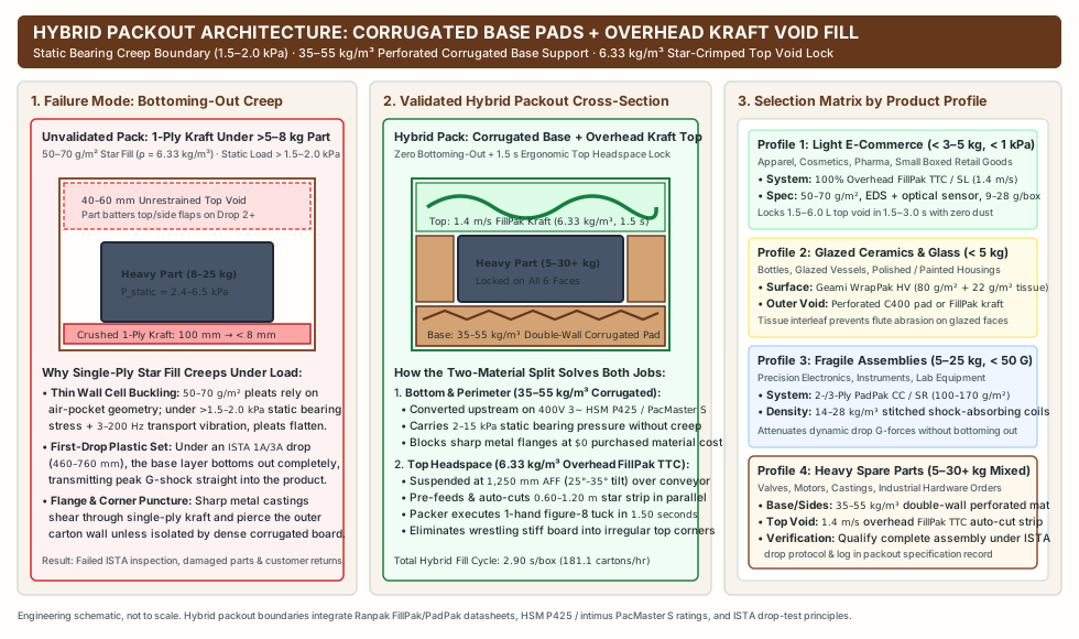
| Shipment Mass, Fragility & Surface Profile | Bottom & Lateral Structural Support Layer | Top Headspace & Irregular Void Layer | Governing Equipment Pairing & Validation Link |
|---|---|---|---|
Profile 1: Light E-Commerce, Apparel, Cosmetics, Pharmaceuticals & Small Boxed Goods (< 3–5 kg, < 1.0 kPa) |
Primary retail box sits directly on carton floor (or thin 0.45 m kraft base coil). |
100% Overhead Star-Crimped Kraft Void Fill (1.5–6.0 L void locked with 0.45–1.50 m strip in 1.5–3.0 s; adds only 9–28 g shipping weight). |
Dedicated Ranpak FillPak TTC / SL (1.4 m/s, 50–70 g/m², EDS + photoelectric sensor) over right-sized cartons (on-demand box sizing guide). |
Profile 2: Glazed Ceramics, Glass Bottles & Scratch-Sensitive Painted Surfaces (< 5 kg) |
Expanded perforated corrugated pad (HSM C400 / P425) or star-crimped kraft in outer void, kept clear of glazed face. |
Die-Cut Honeycomb Surface Wrap + Tissue Interleaf (Ranpak Geami WrapPak HV, 80 g/m² kraft expanded 1.68× at 0–0.75 m/s + 22 g/m² tissue locked directly around item). |
Follow the functional surface-vs-void split in honeycomb paper wrap versus shredded cardboard. |
Profile 3: Medium-to-Heavy Fragile Assemblies & Electronics (5–25 kg, Shock Limit < 40–60 G) |
Multi-Ply Crimped/Stitched Paper Cushion Coils (Ranpak PadPak CC / SR, 2–3 ply 100–170 g/m², 14–28 kg/m³) OR Multi-Layer Bolstered Corrugated Pads. |
Multi-ply perimeter blocking coils or overhead star-crimped top fill once lateral shock clearance (c_x >= r_x) is locked. |
Validate drop G-force attenuation and face clearances under our cardboard cushioning packout validation protocol. |
Profile 4: Heavy Industrial Spare Parts, Castings, Hardware & Mixed Orders (5–30+ kg with Irregular Top Void) |
Pre-Cut Double-Wall Perforated Corrugated Base & Side Pads (35–55 kg/m³) converted upstream on a 400 V 3-phase shredder ($0 reused board cost, zero bottoming-out, isolates sharp metal flanges). |
Overhead Swivel-Boom Kraft Paper Void Fill Dispenser (1.4 m/s FillPak TTC / SL, 6.33 kg/m³) suspended at 1,250 mm AFF to lock variable upper 2–8 L headspace in 1.5 seconds. |
Pair an upstream heavy duty cardboard shredder (see cardboard shredders hub) with an overhead paper void fill machine, and audit combined unit cost in the reuse economics worksheet. |
Pack-station commissioning and acceptance checklist
Before releasing a new or retrofitted paper void fill machine workstation to production, verify these five engineering checkpoints and file the signed record with your corrugated reuse and packout documentation:
- Nozzle Elevation & Tilt Verification: Measure discharge chute height above finished floor (
1,150–1,450 mmAFF,100–250 mmabove the tallest active carton flap) and downward head tilt angle (25°–35°), confirming horizontal grasp distance sits inside350–500 mmwith<= 15°torso rotation (NIOSH 2007-131/ISO 11228-3). - Guarding & Electrical Interlock Check (
OSHA 29 CFR § 1910.212): Confirm the rotary/guillotine shear blade is fully enclosed behind an interlocked discharge chute (stopping drive and cut motors immediately if the front access cover is opened) and verify all floor foot pedals have an intact top steel toe guard (IP54/IP65). EDSEncoder Length & Linear Yield Calibration: ProgramPreset A / B / Cstrip lengths from measured residual void volumes (L_pad_preset = V_void_target ÷ y_vol_per_m), dispense 10 consecutive test strips per preset, and verify cut lengths hold within±15 mmand average installed bulk density stays near6.3–7.5 kg/m³(no bimanual over-crushing).- Infeed Splice & Magazine Alignment: On multi-pack stands (
such as the 4-pack FillPak SL), verify rear guide chute alignment (±5°, bend radiusR >= 150 mm) and test an automatic adhesive-strip pack-to-pack splice transition at1.4 m/swithout web edge tearing. - Packout Acceptance & Bearing Creep Check: For any SKU exceeding
5 kgor1.5 kPabottom contact pressure, confirm high-density (35–55 kg/m³) perforated corrugated base pads or multi-ply (100–170 g/m²) cushioning pads carry the bottom load before applying overhead single-ply kraft void fill.
Technical basis and scope
This workstation engineering and ergonomics guide draws on published manufacturer specifications from the Ranpak FillPak TTC folder (190007_EN_revB), Ranpak FillPak TT folder (190006_EN_revB), Ranpak FillPak SL folder (190012_EN), Ranpak FillPak High-Volume folder (190005_EN_revB), Ranpak PadPak SR (190001_EN_revB) and PadPak CC (190004_EN_revB) folders, the HSM ProfiPack product overview (Revision September 2026), and the intimus PacMaster S / VS data sheet (03/02/2025). Workstation reach envelopes, upper-limb repetitive action thresholds, and machine-guarding rules reference CDC/NIOSH Publication No. 2007-131 (Ergonomic Guidelines for Manual Material Handling), ISO 11228-3 (Handling of low loads at high frequency / OCRA), and OSHA 29 CFR § 1910.212. Verify converter speeds, EDS preset lengths, and drop protection on representative packed assemblies at your packing bench. Return to the void-fill machinery collection hub to coordinate dispenser dosing with packout validation and corrugated reuse workflows.