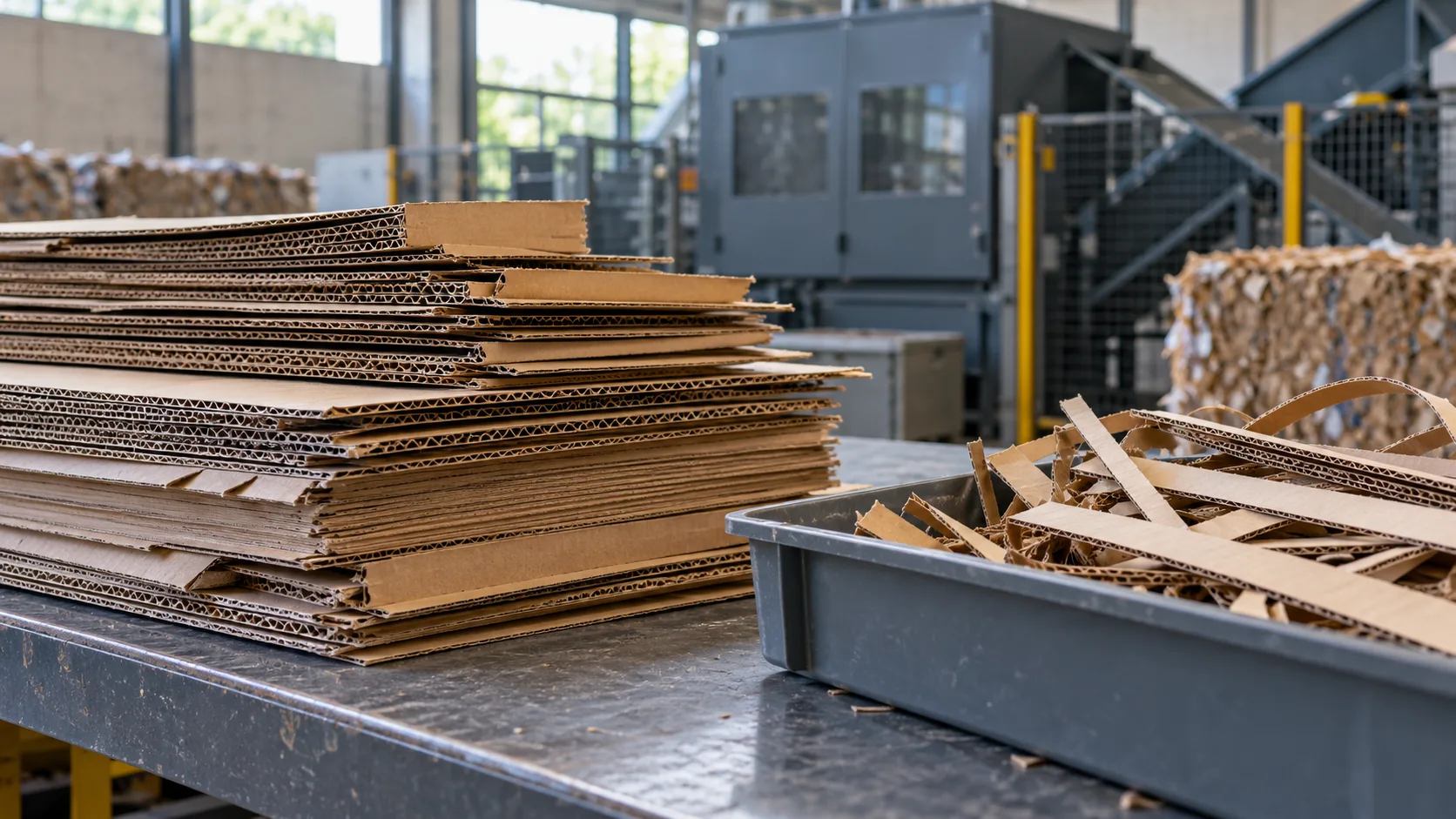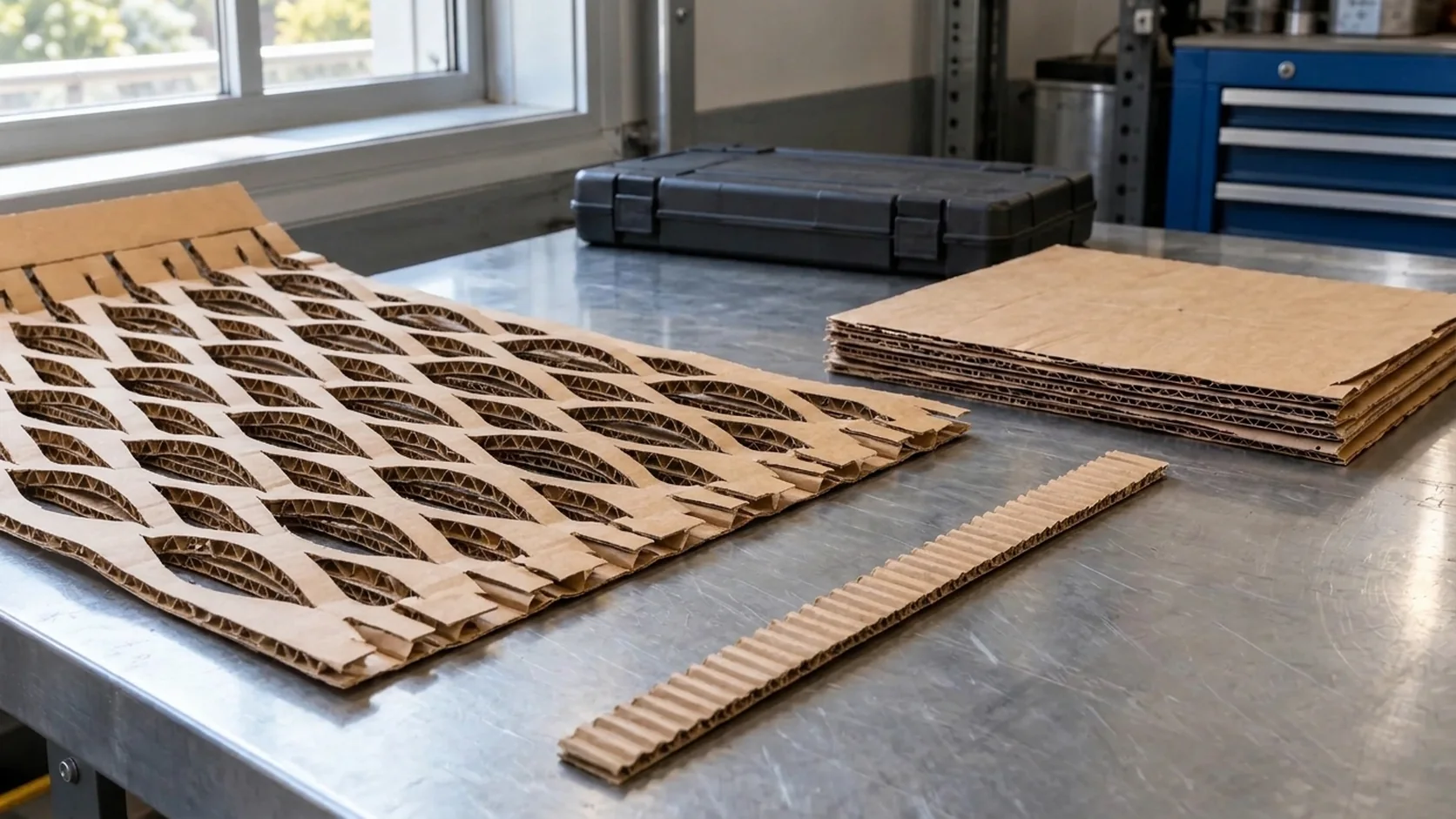
Selecting a heavy duty cardboard shredder for a manufacturing plant, spare-parts depot, or industrial distribution center converting 200+ double-wall corrugated cartons per day (150–450 kg/hr) requires sizing the machine around peak crease shear torque, IEC 60034-1 S1 continuous thermal equilibrium, helical-bevel gearbox heat rejection, and negative-pressure dust extraction velocity. Deploying a light 110V–230V single-phase benchtop or intermittent-duty floor unit against 7–15 mm double-wall (BC, EB, AC, or AA flute) shipping cartons causes repeated rotor stalls on folded box flaps, bimetallic thermal overload downtime, worm-gearbox oil seal leakage, and uncaptured cellulose dust exceeding OSHA 29 CFR § 1910.1000 permissible exposure limits.
Engineering Selection Baseline: Match the powertrain, cutting throat, and dust collector to your heaviest incoming corrugated board grade before comparing published kg/h maximums. A continuous double-wall conversion station requires a 380–415 V / 50 Hz or 460–480 V / 60 Hz 3 phase cardboard shredder (2.2–4.0 kW, IEC 60034-1 S1 continuous duty), an infeed throat gate of >= 20 mm across a >= 425 mm working width, twin counter-rotating 42CrMo4 or AISI D2 (56–60 HRC) hardened cutting rollers driven through a 94%–97% efficient helical-bevel gearbox, and a grounded antistatic extraction manifold (Ø 80–120 mm) maintaining 18–22 m/s (3,500–4,500 FPM) duct transport velocity under 1,500–2,500 Pa static pressure.
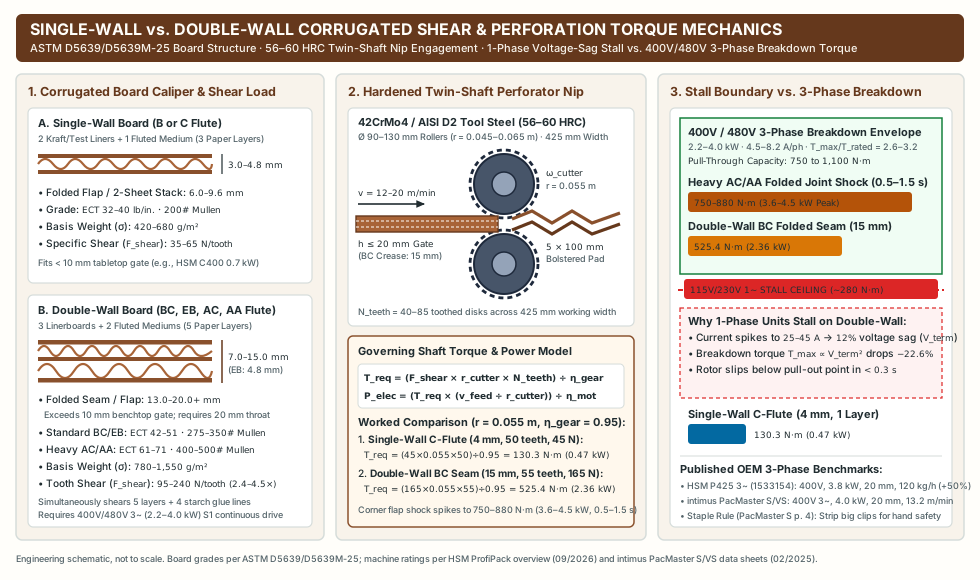
The table below establishes the core engineering parameters separating occasional single-wall converters from industrial 400V / 480V three-phase heavy-duty corrugated perforators across published OEM manuals (HSM ProfiPack C400 / P425 and intimus PacMaster S / VS) and governing industrial standards.
| Subsystem or Parameter | Light / Occasional Single-Phase Tier | Mid-Range Single-Phase AC Floor Tier | Industrial Heavy-Duty 3-Phase Tier (200+ Double-Wall Boxes/Day) |
Governing Standard / OEM Benchmark & Failure Prevention |
|---|---|---|---|---|
| Electrical Supply & Rated Power | 115–230 V, 1-Phase, 50/60 Hz; 0.7–1.1 kW power consumption |
220–240 V, 1-Phase, 50/60 Hz; 1.5–2.0 kW power consumption |
380–415 V / 50 Hz or 460–480 V / 60 Hz 3-Phase; 2.2–4.0 kW (3.0–5.5 HP) |
HSM ProfiPack overview (09/2026, p. 6): C400 (1528134, 230 V, 0.7 kW) vs. P425 AC (1531154, 230 V, 2.0 kW) vs. P425 3-Phase (1533154, 400 V, 3.8 kW); intimus PacMaster S/VS (400 V 3~, 4.0 kW). |
| Permitted Throat Height & Layer Gate | 10 mm max feed height; 1 layer single-wall (B/C flute) |
20 mm max feed height; up to 3 layers (limited by 1-phase stall torque on folded seams) |
20 mm max feed height; up to 3 layers single-wall or 1–2 layers heavy double-wall (BC/EB/AC/AA) |
Enforce the dual intake gate (sheet count n AND stack height h <= 20 mm) defined in our blade types and throughput guide. |
Cutter Shaft Torque Capacity (T_req) |
110–180 N·m continuous (stalls at ~250–280 N·m on folded double-wall seams) |
220–340 N·m continuous (voltage sag triggers auto-reverse on heavy AC/AA creases) |
500–650 N·m continuous; 750–1,100 N·m transient breakdown torque (T_max / T_rated = 2.6–3.2) |
Prevents rotor slip stall during 0.5–1.5 s peak compression when 14–20 mm folded double-wall flaps enter the nip at 12–20 m/min. |
| Motor Duty Cycle & Insulation Class | IEC 60034-1 S2 (30–60 min short-time duty) |
IEC 60034-1 S3 (40%–60% intermittent periodic duty) |
IEC 60034-1 S1 (100% Continuous Running Duty); Class F (155 °C) insulation with Class B (80 K) rise |
IEC 60034-1 S1 reaches thermal equilibrium (dT/dt = 0) at 115–120 °C, leaving a 25 K buffer against paper-dust fin fouling. |
| Overload & Jam Protection Chain | Single-pole thermal cutout switch | Bimetallic breaker + basic current-limit reverse | 3-Tier Chain: VFD/Controller Auto-Reverse (> 1.35 I_FLC) + IEC 60947-4-1 MPCB (phase-loss trip) + Stator PTC (DIN 44081) |
Protects against mechanical nip jams, blown-fuse single-phasing, and blocked motor cooling fan cowls; log trips in maintenance and jam records. |
| Reduction Gearbox Architecture | Spur gear train or grease-packed light worm drive | Compound worm or light helical-worm gearbox (70%–82% efficiency) |
Case-carburized helical-bevel gearbox (eta_gear = 94%–97%, f_B >= 1.5), ISO VG 220 synthetic PAO/PAG oil |
Cuts gearbox friction heat loss by 85% (146 W vs. 987 W on a 3.5 kW shaft load), keeping oil sump at 60–72 °C and preventing NBR seal leaks. |
| Cutter Shaft Metallurgy & Hardness | Carbon steel or surface-hardened stamped blades (42–48 HRC) |
Induction-hardened rollers (52–56 HRC) |
Monolithic or segmented 42CrMo4 (AISI 4140) / X155CrVMo12-1 (AISI D2) rollers at 56–60 HRC |
Resists silica/ash abrasion in recycled linerboard and survives incidental <= 1.2 mm staples (strip heavy crate stitches for packer hand safety). |
| Negative-Pressure Dust Extraction | Unported gravity tray (< 50 kg/h low-dust single-wall) |
Optional side/rear adapter (>= 300 m³/h) |
Integrated Ø 80–120 mm (Ø 100 mm std) port; 18–22 m/s (3,500–4,500 FPM), 509–622 m³/h @ 1,800–2,400 Pa, grounded antistatic PU hose, MERV 14 + HEPA H13 |
Complies with OSHA 29 CFR § 1910.1000 Table Z-1 (15 / 5 mg/m³ cellulose PEL), 29 CFR § 1910.94, and NFPA 652 / 664. |
Double-wall vs single-wall cutting force and 3-phase torque mechanics
Corrugated board structural mechanics (ASTM D5639/D5639M-25)
Under ASTM D5639/D5639M-25 (Standard Practice for Selection of Corrugated Fiberboard Materials and Box Construction Based on Performance Requirements), single-wall shipping cartons consist of one fluted corrugating medium bonded between two linerboards (3 paper layers total). By contrast, double-wall (three-liner, two-medium) industrial cartons stack two fluted mediums—most commonly B+C (BC-flute), E+B (EB-flute), A+C (AC-flute), or A+A (AA-flute)—between an outer kraft linerboard, a central intermediate linerboard, and an inner linerboard (5 paper layers bonded by 4 cured corn-starch adhesive lines).
When a heavy duty corrugated perforator converts incoming cartons into an expanded cushioning mat or bolstered pad, the counter-rotating toothed shafts do not merely slice a flat sheet. They must simultaneously pierce, shear, score, and plastically bulk all five paper layers across 40 to 85 parallel cutting planes while forcing the multi-wall web through a converging compression slider cavity. Because both shear resistance and bending stiffness scale non-linearly with board caliper (t) and virgin/test kraft liner basis weight (σ), transitioning from single-wall C-flute to industrial double-wall BC-flute or heavy export AC/AA-flute increases instantaneous tooth cutting force by 2.4× to 4.5×.
Corrugated Board Profile (ASTM D5639/D5639M-25) |
Layer & Adhesive Construction | Nominal Flat Caliper (t) |
Folded Flap / Taped Seam Stack (2 × t) |
Typical ECT & Mullen Bursting Grade |
Area Basis Weight (σ) |
Specific Tooth Shear & Bulking Force (F_shear) |
Required Machine Throat & Powertrain Tier |
|---|---|---|---|---|---|---|---|
Single-Wall (B or C Flute) |
2 liners + 1 medium (3 paper layers, 2 glue lines) |
3.0–4.8 mm (B: ~3.0 mm; C: ~4.0 mm) |
6.0–9.6 mm (clears 10 mm benchtop gate) |
ECT 32–40 lb/in. (5.6–7.0 kN/m); "200# Mullen" (1,380 kPa) |
420–680 g/m² (0.42–0.68 kg/m²) |
35–65 N per engaged cutter tooth |
Light 115–230 V 1-phase benchtop (0.7–1.5 kW, 10 mm throat, e.g., HSM C400) or 1-phase floor unit for intermittent batches. |
Standard Double-Wall (EB or BC Flute) |
3 liners + 2 mediums (5 paper layers, 4 glue lines) |
4.8–7.5 mm (EB: ~4.8 mm; BC: ~6.5–7.5 mm) |
13.0–15.0 mm (exceeds 10 mm tabletop gate on a single folded crease!) |
ECT 42–51 lb/in. (7.4–8.9 kN/m); "275#–350# Mullen" (1,900–2,410 kPa) |
780–1,100 g/m² (0.78–1.10 kg/m²) |
95–155 N per engaged tooth (2.4×–2.7× single-wall) |
400V / 480V 3-phase floor perforator (2.2–4.0 kW, 20 mm throat, S1 duty); 1-phase 2.0 kW units restricted to flat single sheets without folded seams. |
Heavy Industrial Double-Wall (AC or AA Flute, Heavy Kraft) |
3 heavy kraft liners (300–440 g/m² each) + 2 deep mediums (5 layers) |
8.0–15.0 mm (AC: ~8.5–9.5 mm; AA/export: 10–15 mm) |
16.0–30.0 mm (2 folded layers exceed 20 mm gate -> feed 1 flat blank at a time) |
ECT 61–71 lb/in. (10.7–12.4 kN/m); "400#–500# Mullen" (2,760–3,450 kPa) |
1,150–1,550 g/m² (1.15–1.55 kg/m²) |
160–240 N per engaged tooth (3.5×–4.5× single-wall) |
Dedicated 400V / 480V 3-phase heavy-duty perforator (3.8–4.0+ kW, helical-bevel drive, 20 mm throat, 1 sheet/pass); slit overlapped joints > 20 mm before infeed. |
Cutter shaft torque equation and worked single-wall vs double-wall calculation
To prevent rotor stall when a double-wall carton crease enters the cutting head, the mechanical output torque delivered to the perforating/slitting shafts must exceed the sum of instantaneous shearing, scoring, and compression forces across all engaged cutter disks divided by the transmission efficiency of the reduction gearbox:
T_req = (F_shear × r_cutter × N_engaged_teeth) ÷ η_gear
The corresponding electrical input power (P_elec, in Watts) drawn from the plant branch circuit at linear board feed speed v_feed (m/s, where cutter angular velocity ω_cutter = v_feed ÷ r_cutter in rad/s) and motor efficiency η_motor is:
P_elec = P_shaft ÷ η_motor = (T_req × ω_cutter) ÷ η_motor = (F_shear × N_engaged_teeth × v_feed) ÷ (η_gear × η_motor)
Where:
T_req: Required output torque referred to the cutter shaft (N·m).F_shear: Instantaneous combined shearing, scoring, and bulking force per engaged cutter tooth (N/tooth).r_cutter: Effective pitch radius of the serrated perforating roller (m, typically0.045 to 0.065 mfor aØ 90–130 mmcutting cylinder).N_engaged_teeth: Number of slitting/perforating disks simultaneously engaged across the415–425 mmworking width (typically 40 to 85 disksspaced at5 to 10 mmaxial pitch; for example, the HSM ProfiPack P425 manual (Edition 02/2020, p. 16) specifies a5 × 100 mmperforation grid across its425 mmworking width).η_gear: Mechanical transmission efficiency of the reduction gearbox (0.94–0.97for hardened helical-bevel gearing versus0.70–0.82for sliding worm gearing).v_feed: Linear board feed velocity (m/s, typically0.20 to 0.33 m/s[12 to 20 m/min]; for example, the intimus PacMaster S data sheet (02/2025) specifies220 mm/s=0.22 m/sor13.2 m/min).
Worked Calculation — Scenario A (Single-Wall C-Flute, 4.0 mm Caliper, ECT 32):
Assuming 1 flat sheet fed across N_engaged_teeth = 50 teeth, roller pitch radius r_cutter = 0.055 m (Ø 110 mm), specific tooth force F_shear = 45 N/tooth, gearbox efficiency η_gear = 0.95, linear speed v_feed = 0.20 m/s (12 m/min, ω_cutter = 3.64 rad/s), and motor efficiency η_motor = 0.85:
T_req = (45 × 0.055 × 50) ÷ 0.95 = 130.3 N·mP_shaft = 130.3 N·m × 3.64 rad/s = 474 W(0.47 kWmechanical;P_elec = 0.47 ÷ 0.85 = 0.56 kWelectrical input—well within the0.7 kWrating of a230 Vsingle-phase tabletop unit such as the HSM ProfiPack C400).
Worked Calculation — Scenario B (Double-Wall BC-Flute, 7.5 mm Wall / 15.0 mm Folded Seam, ECT 51 / 350# Mullen):
Feeding a flattened BC-flute carton where a folded flap or taped manufacturer’s joint (15.0 mm stack height, inside the 20 mm throat ceiling) engages N_engaged_teeth = 55 teeth at r_cutter = 0.055 m, F_shear = 165 N/tooth, η_gear = 0.95, v_feed = 0.22 m/s (13.2 m/min, ω_cutter = 4.00 rad/s), and η_motor = 0.89:
T_req = (165 × 0.055 × 55) ÷ 0.95 = 525.4 N·m(4.03×the cutter shaft torque of single-wall board)P_shaft = 525.4 N·m × 4.00 rad/s = 2,101.6 W(2.10 kWmechanical)P_elec = 2,101.6 W ÷ 0.89 = 2,361 W(2.36 kWsustained electrical input), spiking to750–880 N·m(3.6–4.5 kWtransient peak for0.5–1.5 seconds) when an overlapped corner crease or heavyAC/AAglued joint enters the compression throat.
Why 110V–230V single-phase motors stall while 400V/480V 3-phase drives pull through
- Single-Phase Branch Voltage Sag & Quadratic Torque Collapse (
T_max ∝ V_term²): A115 Vor230 Vsingle-phase induction motor (0.75–2.0 kW) relies on an auxiliary capacitor-run winding and draws all power from a single phase-to-neutral branch circuit. When a525–850 N·mdouble-wall crease shock load hits the cutter shafts, single-phase line current surges to25–45 A, inducing an8% to 15%resistive voltage drop (ΔV = I × R_line) along warehouse branch wiring. Because the electromagnetic breakdown (pull-out) torque of an induction motor is strictly proportional to the square of terminal voltage (T_max ∝ V_term²), a12%voltage sag (V_term = 0.88 × V_nominal) immediately reduces available breakdown torque to0.88² = 0.774(a22.6%torque collapse). The motor slips past its breakdown slip point within0.3 seconds, stalls the cutter head, and trips the thermal overload or auto-reverse cycle. - Three-Phase Balanced Rotating Field & Breakdown Torque Envelope (
T_max / T_rated = 2.6–3.2): A380–415 V / 50 Hzor460–480 V / 60 Hz3 phase cardboard shredder(2.2–4.0 kW,IE3 / IE4premium efficiency) distributes load across three balanced phase conductors (L1, L2, L3), drawing only4.5 to 8.2 Aper phase at full load. Three-phase power (P = √3 × V_L × I_L × cos φ) eliminates the100/120 Hztorque pulsation inherent to single-phase stators and provides a breakdown-to-rated torque ratio (T_max / T_rated) of2.6 to 3.2. On a3.8–4.0 kWthree-phase perforator rated at500–550 N·mnominal shaft torque, the motor delivers750 to 1,100 N·mof transient pull-through torque without line voltage sag, shearing straight through15–20 mmdouble-wall creases at a steady12–20 m/min. - Published OEM Throughput Proof (
HSM P425 1-Phase vs 3-Phase&intimus PacMaster S/VS): In HSM’s ProfiPack product overview (Revision September 2026, p. 6), upgrading the exact same425 mmworking width and20 mm / 3-layerP425 chassis from single-phase220–240 V(P425 AC, product1531154,2.0 kWpower consumption) to three-phase400 V / 50 Hz(P425 three-phase, product1533154,3.8 kWpower consumption; labeledmotor power max. 3.8 kWon p. 16 of the 02/2020 P425 operating manual) increases published throughput by+50%—fromup to 80 kg/htoup to 120 kg/h. Likewise, the industrial intimus PacMaster S and PacMaster VS (425 mmworking width,20 mminfeed height,13.2 m/mincutting speed,up to 7 m³/hand11 m³/hvolumetric mat output) are built exclusively on a400 V / 50 Hz 3-phase, 4.0 kWpowertrain fused at16 A–20 Aslow-blow per the PacMaster S operating manual (doc. 88034 11 06/15).
Cutter shaft metallurgy (56–60 HRC) and the staple-handling safety boundary
Recycled double-wall kraft and test linerboards contain 8% to 16% mineral ash—including abrasive silica (SiO₂), kaolin clay, and calcium carbonate (CaCO₃) fillers—alongside occasional metal closure staples. Industrial heavy-duty corrugated perforators use twin counter-rotating shafts machined from through-hardened or inductively case-hardened alloy tool steel (42CrMo4 [AISI 4140] or high-carbon high-chromium X155CrVMo12-1 [AISI D2]) heat-treated to 56–60 HRC (Rockwell C hardness). Both HSM’s inductively hardened solid steel cutting rollers and intimus’s hardened steel cutting cylinders are engineered to shear through standard wire staples (wire diameter <= 1.2 mm) without tooth spalling or edge rollover.
However, procurement engineers and warehouse supervisors must enforce a strict operational boundary between machine cutter survival and finished packout safety:
- As explicitly mandated in the intimus PacMaster S operating manual (Document 88034 11 06/15, English page 4) and reinforced in our cardboard shredder blade types and throughput guide, large metal clips and staples must be removed before feeding because protruding metal fragments in the perforated mat can lacerate packing personnel or scratch packed goods.
- Heavy industrial double-wall export crates (
ACandAAflute,ECT 61–71) are frequently joined with heavy flat-wire copper-clad steel stitches (1.5 to 2.5 mmcrown wire). Install a pre-sort trim knife at the receiving dock (see corrugated reuse workflows) to strip stitched manufacturer’s joints before staging blanks at the perforator infeed, and verify surface-contact clearance under the cardboard cushioning packout validation protocol.
Rules of Thumb — Torque, Throat Gate & Cutter Specification:
- Rule 1 (Single-Folded Double-Wall Throat Gate): If incoming cartons include
BC,AC, orAAdouble-wall board (nominal caliper t >= 6.5 mm), reject any shredder with a maximum feed height< 15–20 mm, because a single folded box flap (2 × t = 13–20 mm) exceeds a10 mmtabletop throat gate before cutting even begins. - Rule 2 (Three-Phase Powertrain Threshold): If daily conversion volume exceeds
80–100 double-wall boxes/day(> 100 kg/day) OR board grade reachesECT >= 44 lb/in.("275# Mullen"), specify a400V / 480V 3-phasedrive (2.2–4.0 kW) delivering>= 500 N·mcontinuous cutter torque; single-phase115V/230Vmotors will suffer voltage-sag stalls on folded creases. - Rule 3 (Dual-Gate Stack Limit on Heavy Double-Wall): Even on a
400V / 3.8–4.0 kWmachine rated for"up to 3 layers and 20 mm"(such as the HSM P425 or intimus PacMaster S), feed8–15 mmheavy double-wall board1 sheet at a time(n = 1), because a 3-sheet stack (3 × 8 mm = 24 mm) violates the20 mmphysical throat gate and triggers auto-reverse stops.
IEC 60034-1 S1 continuous duty, thermal protection, and gearbox cooling
Motor duty classes (IEC 60034-1 S1 vs S2 and S3) and winding insulation margin
A motor’s kilowatt nameplate rating (kW) defines mechanical shaft output during a test cycle, but its IEC 60034-1 (Rotating electrical machines — Part 1: Rating and performance) Duty Type (S1 through S10) governs whether the machine can convert an entire shift’s accumulation of 200 to 600 double-wall boxes without thermal shutdown.
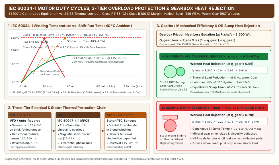
IEC 60034-1 Duty Designation |
Standard Cycle Definition & Thermal Equilibrium State | Double-Wall Box Capacity per 8-Hour Shift | Typical Powertrain & Cooling Architecture | Operational Consequence Under Continuous Two-Operator Feeding |
|---|---|---|---|---|
S1 (Continuous Running Duty) |
Operation at constant rated load for sufficient duration (>= 3–8 hours) to reach full thermal equilibrium (dT/dt = 0) below permissible insulation limits. |
200 to 600+ double-wall boxes/shift (150–450 kg/hr over 2–6+ hours nonstop). |
400V / 480V 3-phase, 2.2–4.0 kW (IE3 / IE4), IP54 / IP55 TEFC enclosure (IC411 shaft fan or IC416 forced blower), Class F insulation with Class B rise, helical-bevel oil-bath gearbox. |
Runs continuously through gaylord/pallet batches without thermal trips; windings stabilize at 115–120 °C (40 °C ambient). |
S2 (Short-Time Duty, e.g., S2 30 min or S2 60 min) |
Operation at constant load for a stated period (30 or 60 min), less than required to reach equilibrium, followed by a de-energized rest period until machine cools within 2 K of ambient (45–90 min). |
30 to 70 boxes per batch before mandatory 45–90 min cooldown lockout. |
115V / 230V 1-phase, 0.7–1.5 kW compact benchtop or light mobile units with grease-packed spur or worm gears. |
Winding temperature climbs steeply at 2.5–3.5 °C/min under double-wall load, tripping thermal protection at 25–45 minutes and idling the packing line. |
S3 (Intermittent Periodic Duty, e.g., S3 40% or S3 60%) |
Sequence of identical 10-minute duty cycles (e.g., 4 min ON at rated load followed by 6 min OFF de-energized for S3 40%). |
60 to 120 boxes/shift only if operators strictly pace feeding (pausing 4–6 min every 10 min). |
Single-phase 1.5–2.0 kW AC floor perforators operated near their 20 mm thickness ceiling. |
Cumulative heat ratchets upward across consecutive 10-min cycles when staged pallets are fed continuously, tripping the thermal cutout within 25–35 minutes. |
For industrial corrugated conversion bays where ambient summer temperatures reach 35–40 °C and airborne cellulose lint can coat motor cooling fins, specify IEC 60034-1 Insulation Class F (155 °C maximum permissible hot-spot temperature) engineered for Class B temperature rise (ΔT <= 80 K at 40 °C ambient = 120 °C winding temperature, plus 10–15 °C hot-spot allowance). That 25 K (25 °C) thermal safety margin between the 120 °C Class B operating ceiling and the 145–155 °C Class F limit doubles stator varnish life for every 10 K reduction in operating temperature (per the Arrhenius half-life rule) and prevents nuisance cutouts during peak seasonal shipping surges.
Three-tier overload protection chain: Auto-reverse, IEC 60947-4-1 MPCB, and stator PTC thermistors
Relying on a single push-to-reset bimetallic button is insufficient for a 400V / 480V heavy-duty shredder. Industrial three-phase corrugated perforators integrate a coordinated three-tier protection hierarchy that separates mechanical over-thickness jams from electrical phase faults and cooling-fan fouling:
- Tier 1 — VFD / Controller Current-Limit Auto-Reverse (
0.3–0.5 sPre-Trip Anti-Jam): When an operator feeds an overlapped double-wall flap or folded corner that exceeds the20 mmnip clearance, stator phase current (I_phase) spikes above135% to 150%of rated full-load current (I_FLC). Within0.3 to 0.5 seconds—well before mechanical shaft seizure or thermal trip occurs—the variable-frequency drive (VFD) or electronic reversing contactor halts forward rotation, pauses100–200 msto allow rotor inertia to decay, and reverses the cutting rollers for2 to 3 secondsto back the jammed carton blank out of the infeed throat. - Tier 2 —
IEC 60947-4-1Motor Protection Circuit Breaker (MPCB,< 3.0 sPhase-Loss & Overload Trip): Mounted inside the main400V / 480Vcontrol cabinet, anIEC 60947-4-1MPCB provides three-pole ambient-compensated bimetallic overload protection (Trip Class 10AorClass 10, tripping within2–10 secondsat7.2 × I_FLClocked-rotor current), instantaneous magnetic short-circuit interruption (12–14 × I_n), and differential phase-loss / phase-unbalance sensitivity. If one of the three upstream facility fuses (16 A–20 Aslow-blow) opens during operation, a three-phase motor attempting to pull a3.5 kWdouble-wall load on two phases (“single-phasing”) draws173%(√3) current in the remaining windings; the MPCB differential mechanism trips in< 3 secondsto prevent stator burnout. - Tier 3 — Embedded Stator Winding
PTCThermistors (DIN 44081 / IEC 60034-11,145–150 °CDirect Thermal Cutoff): An external current-sensing breaker (MPCB) measures current (I), not actual copper winding temperature (T_winding). In a corrugated shredding area, fine cellulose fibers can blanket the motor’s rearIC411fan cowl, starving airflow so the stator overheats above150 °Ceven while pulling only85%rated current. Embedding three positive-temperature-coefficient (PTC) thermistors directly into the three stator end-windings (wired in series to a safety thermistor relay at a 145–150 °C Curie switch point) drops out the main contactor whenever actual winding temperature approaches theClass Flimit, locking out restarts until the windings cool below the reset hysteresis threshold (115–125 °C).
As detailed in the HSM ProfiPack P425 operating instructions (Edition 02/2020, p. 15) and the intimus PacMaster S manual (doc. 88034 11 06/15), operators and maintenance technicians must distinguish between a Tier 1/2 mechanical over-thickness jam (cleared via the reverse push-button and sheet-thickness reduction) and a Tier 3 motor thermal overload cutout (which requires waiting for the thermal reset interval and inspecting cooling air intakes). Log every stoppage symptom, board presentation, and reset outcome in your workstation’s cardboard shredder maintenance and jam records.
Gearbox mechanical efficiency and oil-sump heat rejection: Helical-bevel vs sliding worm gears
Electric motor duty class is only half of the continuous-run thermal equation. The reduction gearbox (reducing 1,450–1,750 RPM 4-pole motor speed down to 35–55 RPM at the cutter shafts, reduction ratio i = 25:1 to 40:1) converts every percentage point of mechanical inefficiency (1 − η_gear) directly into friction heat inside the gearbox oil sump:
Q_gear_loss = P_shaft × ((1 − η_gear) ÷ η_gear)
Where Q_gear_loss is internal friction heat generation (W), P_shaft is mechanical power delivered to the cutter shafts (W), and η_gear is the fractional mechanical efficiency of the gear train.
Worked Thermal Dissipation Comparison at P_shaft = 3,500 W (3.5 kW Heavy Double-Wall Load):
- Configuration A — Sliding Worm Gearbox (
η_gear = 0.78[70%–82%range]): Right-angle worm gearboxes transmit torque via high-velocity sliding contact between a hardened steel worm shaft and a phosphor-bronze worm wheel. Atη_gear = 0.78:Q_gear_loss = 3,500 W × ((1 − 0.78) ÷ 0.78) = 3,500 W × 0.2821 = 987.2 W(nearly1.0 kWof continuous heat trapped inside a compact aluminum gearbox housing!). Because an uncooled worm housing of0.35–0.45 m²surface area coated with a thin layer of insulating cardboard dust can only dissipate~350–450 Wby natural convection at an80 °Csump temperature, continuousS1double-wall operation drives the worm oil sump past95 to 110 °Cwithin60–90 minutes. At> 95 °C, standard mineral gear oil oxidizes rapidly, nitrile (NBR) shaft lip seals harden and crack, gear oil leaks onto the perforated cardboard mats, and the bronze wheel teeth suffer accelerated pitting and stripping under crease shock loads. - Configuration B — Hardened Helical or Helical-Bevel Gearbox (
η_gear = 0.96[94%–97%range]): Industrial inline helical (R-series) or right-angle helical-bevel (K-series) gearmotors transmit torque via rolling contact across case-carburized, ground alloy-steel gear teeth (58–62 HRC). Atη_gear = 0.96:Q_gear_loss = 3,500 W × ((1 − 0.96) ÷ 0.96) = 3,500 W × 0.0417 = 145.8 W(an85.2%reduction in internal heat generation compared to the worm gearbox!). Generating only146 Wof heat and filled withISO VG 220synthetic polyalphaolefin (PAO) or polyalkylene glycol (PAG) lubricant paired with fluoroelastomer (FKM / Viton) shaft seals and a mechanical service factorf_B >= 1.5, the helical-bevel oil sump stabilizes at a safe60 to 72 °Cacross multi-shift continuous operation.
Rules of Thumb — Thermal Duty & Gearbox Selection:
- Rule 1 (
S1+ Class F/B Mandate): For any station converting>= 150 double-wall boxes/day(>= 1.5 hours/dayactive cutting), requireIEC 60034-1 S1duty +Class Finsulation withClass B (80 K)temperature rise + embeddedDIN 44081 PTCthermistors on the motor nameplate. - Rule 2 (Helical-Bevel Gearbox Mandate): Reject single-stage or compound sliding worm gearboxes (
η_gear < 85%) on>= 2.2 kWcontinuous-duty shredders; specify a hardened helical or helical-bevel gearbox (η_gear >= 94%, service factorf_B >= 1.5) to keep oil sump temperatures< 75 °Cwithout auxiliary oil coolers.
Negative-pressure dust extraction sizing and OSHA/NFPA cellulose dust safety
Why double-wall slitting multiplies airborne cellulose and starch dust (1.5–4.5 g/kg)
Converting double-wall (BC, EB, AC, AA) corrugated cartons generates 2.5× to 4.0× more airborne dust per kilogram of board than single-wall conversion. While outer kraft linerboards contain long virgin softwood sulfate fibers (2.5–4.0 mm fiber length) that shear cleanly, the two internal fluted corrugating mediums are manufactured primarily from recycled neutral sulfite semi-chemical (NSSC) hardwood and old corrugated containers (OCC) rich in short brittle fibers (< 0.8 mm), fines, and mineral fillers, bonded to three liners along four cured corn-starch adhesive ridges.
When the 56–60 HRC serrated rollers shear, score, and crush those two fluted mediums at 12–20 m/min, the brittle starch glue lines shatter and release 1.5 to 4.5 grams of dry cellulose dust and starch particulates (10–250 µm particle size distribution) per kilogram of processed double-wall board. On an industrial 3 phase cardboard shredder processing 200 kg/hr (~150 double-wall cartons/hr), operating without negative-pressure extraction releases 300 to 900 g/hr of airborne cellulose dust directly into the operator breathing zone, motor cooling cowl, and warehouse rafters.
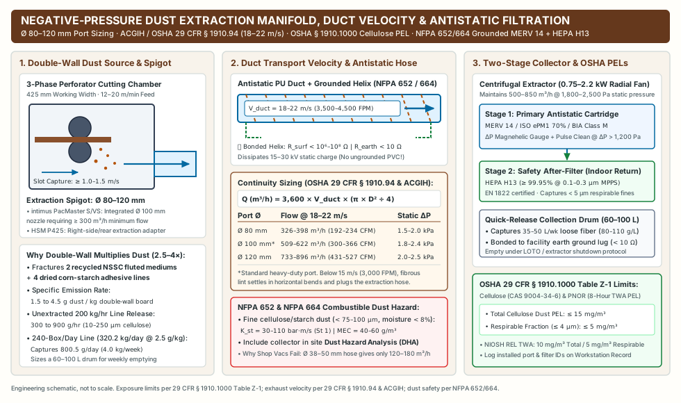
Fluid mechanics of dust port sizing (Ø 80–120 mm) and minimum duct transport velocity (18–22 m/s)
Under OSHA 29 CFR § 1910.94 (Ventilation) and the ACGIH Industrial Ventilation: A Manual of Recommended Practice for Design, local exhaust ventilation (LEV) systems conveying dry paper dust, cardboard lint, and fibrous cellulose particulates must maintain two simultaneous fluid-dynamic thresholds:
- Inward Hood Slot Capture Velocity (
V_capture >= 1.0–1.5 m/s[200–300 FPM]): The dust extractor must maintain sufficient negative pressure inside the shredder’s lower cutting chamber so air flows inward through the425 mm × 20 mminfeed throat and mat discharge chute at>= 1.0–1.5 m/s, arresting fine dust kickback against the12–20 m/min(0.20–0.33 m/s) web movement. - Minimum Duct Transport Velocity (
V_duct = 18 to 22 m/s[3,500 to 4,500 FPM]): Inside all horizontal and inclined extraction hoses and ducts, air velocity must never fall below18 m/s(3,540 FPM). If duct velocity drops below15 m/s(3,000 FPM), fibrous paper lint and starch particulates settle out inside horizontal hose corrugations and elbows, progressively constricting the duct cross-section until suction collapses and a dense combustible fiber plug forms.
By volumetric continuity, required extraction airflow Q (m³/h) through a circular extraction spigot of internal diameter D (m) and cross-sectional area A_duct = (π × D²) ÷ 4 (m²) at target transport velocity V_duct (m/s) is:
Q (m³/h) = 3,600 × V_duct × A_duct = 3,600 × V_duct × ((π × D²) ÷ 4)
(To convert Q from m³/h to CFM [cubic feet per minute], divide m³/h by 1.699 or multiply by 0.5886.)
Worked Calculation — Standard Ø 100 mm (D = 0.100 m, 4 in.) Industrial Perforator Port at V_duct = 20 m/s (3,937 FPM):
- Duct cross-sectional area:
A_duct = (3.1416 × 0.100²) ÷ 4 = 0.007854 m² - Required extraction volume flow:
Q = 3,600 s/h × 20 m/s × 0.007854 m² = 565.5 m³/h(332.8 CFM) - Notice how this engineering transport calculation (
509–622 m³/hacross the18–22 m/sdesign band) sits cleanly above the>= 300 m³/hminimum extraction requirement published on the intimus PacMaster S / VS data sheet (02/2025) for its integratedØ 100 mmrear nozzle, providing the pressure and velocity margin needed to overcome flexible hose friction and filter cake build-up over a full shift.
Extraction Manifold Spigot Diameter (D) |
Internal Duct Area (A_duct) |
Target Duct Transport Velocity (V_duct, ACGIH / 29 CFR § 1910.94) |
Required Volumetric Airflow (Q in m³/h and CFM) |
Required Operating Static Pressure (ΔP_static) |
Matching Perforator Tier & Ducting Envelope |
|---|---|---|---|---|---|
Ø 80 mm (3.15 in.) |
0.00503 m² |
18–22 m/s (3,540–4,330 FPM) |
326–398 m³/h (192–234 CFM) |
1,500–2,000 Pa (6.0–8.0 in. wg) |
Compact 3-phase perforators (<= 425 mm width, 100–180 kg/hr), short flexible antistatic hose run (<= 3.0 m). Exceeds 300 m³/h OEM baseline. |
Ø 100 mm (3.94 in. / 4 in.) |
0.00785 m² |
18–22 m/s (3,540–4,330 FPM) |
509–622 m³/h (300–366 CFM) |
1,800–2,400 Pa (7.2–9.6 in. wg) |
Standard heavy-duty 3-phase port (e.g., intimus PacMaster S/VS integrated Ø 100 mm rear spigot; HSM P425 right-side/rear extraction apparatus) converting 200–350 double-wall boxes/day (<= 5.0 m duct run). |
Ø 120 mm (4.72 in. / 5 in.) |
0.01131 m² |
18–22 m/s (3,540–4,330 FPM) |
733–896 m³/h (431–527 CFM) |
2,000–2,500 Pa (8.0–10.0 in. wg) |
Wide-throat (500–700 mm) or high-speed (20 m/min) heavy-duty shredders (300–450 kg/hr) tied into a central baghouse or cyclone + cartridge collector. |
Why commercial shop vacuums and low-pressure axial blowers fail
Two common improvisation errors cause dust-extraction failures on heavy-duty corrugated perforators:
- Failure Mode 1 — High-Vacuum, Low-Flow Commercial Shop Vacs (
Ø 38–50 mmHose): A wet/dry shop vacuum generates high sealed suction (15,000–22,000 Pa) using a universal brush motor (IEC S2intermittent duty), but its narrowØ 38–50 mmhose restricts volumetric flow to120–180 m³/h(70–105 CFM). Connected via a step-up adapter to aØ 100 mmshredder manifold, velocity inside theØ 100 mmtransition drops to4.2–6.3 m/s(causing immediate fiber plugging), inward capture velocity across the425 mmcutting chamber collapses below0.3 m/s, and the fine pleated paper cartridge blinds with corn-starch fines within20 minutes. - Failure Mode 2 — High-CFM, Low-Pressure Axial Ventilation Fans (
< 300 Pa): In-line axial duct fans advertise800–1,200 m³/hat zero static pressure (free air), but corrugated polyurethane flex hose imposes120–180 Pa/mof friction loss at20 m/s, two90°bends add250 Pa, the perforator hood entry loss adds350 Pa, and a loadedMERV 14filter adds800–1,200 Pa(total system resistanceΔP_static = 1,800–2,400 Pa). Against2,000 Pa, an axial fan stalls completely. Always specify a 3-phase radial/centrifugal industrial dust extractor (0.75–2.2 kWbackward-inclined or radial-blade impeller) rated to deliver500–850 m³/hat1,800–2,500 Paoperating static pressure.
OSHA 29 CFR § 1910.1000 Table Z-1 cellulose PELs and NFPA 652 / 664 combustible dust controls
Operating a high-throughput double-wall shredding station inside an enclosed warehouse triggers mandatory federal occupational exposure and combustible-dust engineering controls:
- Mandatory
OSHA 29 CFR § 1910.1000Table Z-1 Cellulose Exposure Limits: Under 29 CFR § 1910.1000 Table Z-1 (Limits for Air Contaminants), airborne Cellulose (CAS 9004-34-6) and Particulates Not Otherwise Regulated (PNOR) are governed by legally enforceable 8-hour Time-Weighted Average (TWA) Permissible Exposure Limits (PELs):- Total Cellulose Dust PEL:
15 mg/m³(8-hour TWA) - Respirable Fraction PEL (
aerodynamic diameter <= 4 µm):5 mg/m³(8-hour TWA) (Note: The NIOSH Pocket Guide to Chemical Hazards establishes an even stricter Recommended Exposure Limit [REL] of10 mg/m³Total Dust and5 mg/m³Respirable Dust over an 8-to-10-hour TWA.)
- Total Cellulose Dust PEL:
- Combustible Cellulose Dust Deflagration Hazard (
NFPA 652&NFPA 664): While expanded corrugated mats and coarse paper strips (> 500 µm) are not an explosion hazard, the fine dry cellulose and corn-starch adhesive fraction (particle size < 75–100 µm, moisture content< 8%) concentrated inside a dust collector filter chamber is a ClassSt 1combustible organic dust with a deflagration indexK_stof30 to 110 bar·m/s, a maximum explosion pressureP_maxof7.5–9.0 bar, and a Minimum Explosible Concentration (MEC) of40–60 g/m³. Under NFPA 652 (Standard on the Fundamentals of Combustible Dust) and NFPA 664 (Standard for the Prevention of Fires and Explosions in Wood Processing and Woodworking Facilities, applicable to cellulosic fiber processing), facilities must include the corrugated shredder extraction system in their site Dust Hazard Analysis (DHA). - Antistatic Grounded Extraction Ducting (
Preventing 15–30 kV Triboelectric Spark Ignition): Dry cellulose fibers transported at18–22 m/sthrough ungrounded plastic piping generate15 to 30 kVof triboelectric static charge, capable of discharging an electrostatic spark directly into the dust-laden airstream or shocking operators. Never connect a heavy-duty cardboard shredder with ungrounded PVC drain pipe or non-conductive plastic hose. Specify antistatic polyurethane (PU) ducting with an embedded copper-plated spring-steel wire helix (surface resistance < 10⁶ to 10⁸ ΩperISO 8031 / TRGS 727) or spiral-seamed galvanized steel ducting. Strip and bond both ends of the internal wire helix to the perforator chassis earth terminal and the dust collector ground lug (verified earth continuity resistance < 10 Ω). - Two-Stage Filtration (
MERV 14+HEPA H13) for Indoor Warehouse Air Recirculation: When filtered air is returned indoors to conserve heated or air-conditioned warehouse air rather than exhausted outdoors, single-stage felt bags allow< 5 µmrespirable cellulose fines to pass back into the workspace. Specify a two-stage industrial extractor:- Stage 1 Primary Filter: Antistatic aluminized or PTFE-membrane spunbond polyester cartridge/pocket filter (
MERV 14/ISO 16890 ePM1 70%/EN 60335-2-69 Dust Class M) equipped with a differential-pressure (ΔP) magnehelic gauge and manual shaker or automatic compressed-air pulse-jet cleaning triggered whenΔP > 1,200–1,500 Pa. - Stage 2 Safety After-Filter:
HEPA H13(>= 99.95%capture efficiency at0.1–0.3 µmMost Penetrating Particle Size perEN 1822) downstream of the blower, guaranteeing that recirculated air remains below< 0.5 mg/m³(< 10%of the5 mg/m³OSHA respirable PEL). Record the installed adapter part number, hose route, and filter specifications using our cardboard perforator dust extraction and workstation interface record.
- Stage 1 Primary Filter: Antistatic aluminized or PTFE-membrane spunbond polyester cartridge/pocket filter (
Worked sizing model and engineering specification for 200+ double-wall boxes per day
To demonstrate how the torque, IEC 60034-1 S1 duty cycle, useful mass-balance throughput, and dust-extraction continuity equations fit together before issuing a purchase order, consider an industrial spare-parts distribution center repurposing 240 incoming double-wall (BC-flute, 7.0 mmnominal caliper,ECT 48 lb/in.) shipping cartons per 8-hour shift into protective void-fill and cushioning mats (replacing virgin plastic bubble wrap and foam peanuts at the downstream void-fill workstation or pairing high-density bottom pads with an overhead paper void fill machine).
Step 1: Daily incoming double-wall board mass (M_in) and useful mat output (M_useful)
- Average flattened carton blank dimensions (
e.g., 600 × 400 × 400 mmRegular Slotted ContainerRSC): blank areaA_box = 1.45 m²/box. - Measured double-wall
BC-flutearea basis weight:σ = 0.92 kg/m²(920 g/m²). - Mass per double-wall carton (
m_box):m_box = A_box × σ = 1.45 m² × 0.92 kg/m² = 1.334 kg/box - Total daily incoming double-wall feed (
240 boxes/day):M_in = 240 boxes/day × 1.334 kg/box = 320.16 kg/day - Accounting for
10%side-trim and stitched/damaged flap removal during pre-sorting (useful yield fraction y = 0.90):M_useful = 320.16 kg/day × 0.90 = 288.14 kg/dayof accepted double-wall cushioning mats.
Step 2: Net useful throughput (Q_useful) and required IEC 60034-1 S1 shift operating hours (t_shift)
Applying the dimensional workstation mass-balance equation from our cardboard shredder blade types and throughput guide:
Q_useful = 60 × v × w × σ × n × u × y
For an industrial 400 V / 50 Hz 3-phase heavy-duty corrugated perforator (3.8–4.0 kW, 425 mm working width, 20 mm throat height):
- Linear cutting speed:
v = 13.2 m/min(0.22 m/s, matching the intimus PacMaster S rating) - Effective processed width:
w = 0.425 m(excess carton width automatically slit off by the side cutter) - Double-wall basis weight:
σ = 0.92 kg/m² - Simultaneous sheet count:
n = 1 sheet(because a single flattened7.0 mmBC-flutecarton blank presents two overlapped wall thicknesses =14.0 mm, plus~16–18 mmacross taped flap seams, safely inside the20 mmthroat gate; feeding 2 flattened cartons simultaneously would reach28 mm > 20 mmand jam!) - Operator feeding utilization fraction:
u = 0.45(27 minutesof active nip feeding per60-minuteattended workstation hour, absorbing carton staging, staple inspection, mat folding, and cart transfer) - Useful material yield fraction:
y = 0.90
Worked Throughput & Run-Time Calculation:
- Instantaneous gross cutting rate (
at u = 1.0, y = 1.0):Q_instant = 60 min/h × 13.2 m/min × 0.425 m × 0.92 kg/m² × 1 = 309.67 kg/h - Sustained net useful mat throughput (
at u = 0.45, y = 0.90):Q_useful = 309.67 kg/h × 0.45 × 0.90 = 125.42 kg/h(139.35 kg/hraw double-wall board processed) - Required daily active machine run time for
240 double-wall boxes/day:t_shift = M_useful ÷ Q_useful = 288.14 kg/day ÷ 125.42 kg/h = 2.30 hours/day(138 minutes/dayof continuousIEC 60034-1 S1operation, leaving ample single-shift capacity to scale up to500–650 double-wall boxes/daywithout thermal lockout).
Step 3: Specific energy intensity (kWh/kg), dust collector bin sizing, and TCO drivers
When transferring workstation metrics into the cardboard shredder cost and reuse economics model, include both the 400 V 3-phase perforator drive (2.4 kW average electrical draw during active cutting, 0.4 kW idle between sheets -> ~1.65 kW weighted average) and the 1.5 kW centrifugal dust extractor (1.35 kW continuous draw) inside the system boundary (P_sys_avg = 3.00 kW):
- Daily workstation electrical energy (
E_dayover2.30 h):E_day = 3.00 kW × 2.30 h/day = 6.90 kWh/day - Specific energy intensity per useful kilogram of double-wall padding:
e_specific = 6.90 kWh/day ÷ 288.14 kg/day = 0.024 kWh/kg - Captured cellulose dust mass & collection drum volume (
at 2.5 g dust / kg double-wall board):m_dust_day = 320.16 kg/day × 2.5 g/kg = 800.4 g/day(0.80 kg/dayor4.00 kg/weekacross a 5-day week). At a loose fibrous bulk density of80 to 110 g/L,4.00 kg/weekoccupies36 to 50 liters/week, sizing a60 to 100 Lquick-release steel collection drum under the cyclone/cartridge extractor so filter emptying aligns with weekly scheduled housekeeping rather than interrupting mid-shift packing.
Industrial procurement specification and commissioning verification checklist
Use the five-subsystem engineering acceptance matrix below to audit candidate machines during vendor evaluation, factory acceptance testing (FAT), and site commissioning. If you are still evaluating whether your packout requires connected slit-expanded mats versus loose chipped fill, run the sample trial in our cardboard shredder vs perforator comparison first.
| Subsystem | Minimum Heavy-Duty Specification (200+ Double-Wall Boxes/Day) |
Disqualifying Light / Intermittent Specification | Site Commissioning & Nameplate Verification Method |
|---|---|---|---|
| 1. Electrical Supply & Motor Duty Class | 380–415 V / 50 Hz or 460–480 V / 60 Hz 3-Phase, 2.2–4.0 kW (3.0–5.5 HP), IEC 60034-1 S1 (100% Continuous Running Duty), IE3 / IE4 efficiency, IP54 / IP55 TEFC enclosure (IC411 / IC416), Class F (155 °C) insulation with Class B (80 K) temperature rise. |
110–230 V single-phase < 2.0 kW, or any motor stamped S2 (30–60 min) or S3 (40%–60%) intermittent duty. |
Inspect physical motor type-plate for 3~, S1, Ins. Cl. F (ΔT = B / 80K), and IE3/IE4; verify balanced phase currents (< 5% unbalance) under double-wall load with a clamp ammeter. |
| 2. Winding & Circuit Overload Protection | 3-Tier Protection: VFD or controller current-limit auto-reverse (I > 1.35–1.50 I_FLC) + IEC 60947-4-1 Motor Protection Circuit Breaker (MPCB, Class 10A/10 + phase-loss trip) + embedded stator PTC thermistors (DIN 44081). |
Single-pole thermal push-button breaker without phase-loss protection or stator winding thermistor sensing. | Audit electrical schematic; verify MPCB dial setting matches motor I_FLC; test auto-reverse response (0.3–0.5 s) using a > 22 mm test stack and log in maintenance records. |
| 3. Reduction Gearbox & Lubrication | Case-carburized helical or helical-bevel gearbox (η_gear = 94%–97%, 58–62 HRC gears), mechanical service factor f_B >= 1.5, filled with ISO VG 220 synthetic PAO or PAG gear oil and FKM (Viton) shaft seals. |
Single-stage or compound sliding worm gearbox (η_gear = 70%–82%) filled with standard mineral oil (overheats > 95 °C under continuous double-wall load). |
Inspect gearbox manufacturer nameplate (type K/R, ratio i, service factor f_B, lubricant grade); measure housing equilibrium temperature (must stay < 75 °C via IR thermography after a 2-hour S1 run). |
| 4. Throat Geometry & Cutter Metallurgy | >= 425 mm working width with automatic side-trim slitter; >= 20 mm infeed throat height; twin monolithic or segmented 42CrMo4 / AISI D2 (56–60 HRC) hardened cutting rollers running at 12–20 m/min. |
< 15 mm throat height (blocks folded double-wall flaps), unhardened carbon-steel shafts (< 45 HRC), or absence of side cut-off blade. |
Verify OEM manual feed-height/layer table; run a 50-carton trial using your facility’s heaviest folded BC / AC double-wall cartons; enforce pre-sort removal of heavy stitches (PacMaster S manual p. 4). |
| 5. Negative-Pressure Dust Extraction & Grounding | Integrated Ø 80–120 mm (Ø 100 mm std) extraction spigot coupled to a centrifugal collector delivering 18–22 m/s (3,500–4,500 FPM) duct velocity (509–622 m³/h at 1,800–2,400 Pa for Ø 100 mm), grounded antistatic PU hose (< 10⁶ Ω), and MERV 14 + HEPA H13 two-stage filtration. |
Unported gravity tray, commercial shop vacuum (Ø 38–50 mm, < 200 m³/h), ungrounded PVC pipe, or unfiltered indoor air return. |
Measure duct velocity (>= 18 m/s) with a hot-wire anemometer/pitot tube; verify hose-to-ground continuity (< 10 Ω) with a multimeter; log configuration in the dust extraction interface record. |
Technical basis and scope
This engineering selection reference draws on published manufacturer specifications from the HSM ProfiPack product overview (Revision September 2026, pp. 3–7), the HSM ProfiPack P425 operating instructions (Edition 02/2020, English pp. 11–16), the intimus PacMaster S / VS data sheet (03/02/2025), and the intimus PacMaster S operating manual (Document 88034 11 06/15, English p. 4). Corrugated board classifications reference ASTM D5639/D5639M-25; motor duty and thermal insulation classes follow IEC 60034-1 and IEC 60947-4-1; occupational cellulose dust limits and exhaust transport velocities follow OSHA 29 CFR § 1910.1000 Table Z-1, OSHA 29 CFR § 1910.94, NFPA 652, and NFPA 664. Verify all electrical, mechanical, and extraction parameters against the governing type-plate and operating manual of your installed machine. Return to the cardboard shredders collection hub to connect machine specification with output trials, dust interface records, and maintenance logging.